IRF7811WPBF Ver la hoja de datos (PDF) - International Rectifier
Número de pieza
componentes Descripción
Lista de partido
IRF7811WPBF Datasheet PDF : 6 Pages
| |||
PD- 95023C
IRF7811WPbF
HEXFET® Power MOSFET for DC-DC Converters
• N-Channel Application-Specific MOSFETs
• Ideal for CPU Core DC-DC Converters
• Low Conduction Losses
• Low Switching Losses
• 100% Tested for Rg
• Lead-Free
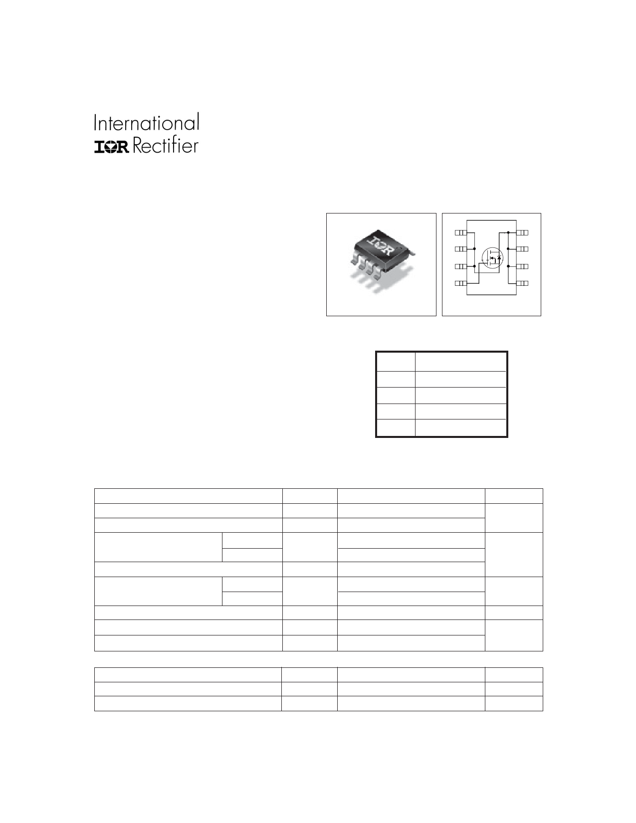
S
1
S
2
S
3
A
8
D
7
D
6
D
Description
This new device employs advanced HEXFET Power
MOSFET technology to achieve an unprecedented
balance of on-resistance and gate charge. The reduced
conduction and switching losses make it ideal for high
efficiency DC-DC converters that power the latest
generation of microprocessors.
The IRF7811WPbF has been optimized for all parameters
that are critical in synchronous buck converters including
RDS(on), gate charge and Cdv/dt-induced turn-on immunity.
The IRF7811WPbF offers particulary low RDS(on) and high
Cdv/dt immunity for synchronous FET applications.
The package is designed for vapor phase, infra-red,
convection, or wave soldering techniques. Power
dissipation of greater than 3W is possible in a typical
PCB mount application.
SO-8
G
4
5
D
Top View
DEVICE CHARACTERISTICS
RDS(on)
QG
Qsw
Qoss
IRF7811WPbF
9.0mΩ
22nC
10.1nC
12nC
Absolute Maximum Ratings
Parameter
Symbol
IRF7811WPbF
Units
Drain-Source Voltage
VDS
30
V
Gate-Source Voltage
VGS
±12
Continuous Drain or Source T = 25°C
I
14
A
D
Current (VGS ≥ 4.5V)
TL = 90°C
13
A
Pulsed Drain Current
IDM
109
Power Dissipation
TA = 25°C
PD
3.1
W
TL = 90°C
3.0
Junction & Storage Temperature Range
TJ, TSTG
–55 to 150
°C
Continuous Source Current (Body Diode)
I
3.8
A
S
Pulsed Source Current
ISM
109
Thermal Resistance
Parameter
Maximum Junction-to-Ambient
RθJA
Maximum Junction-to-Lead
RθJL
www.irf.com
Max.
40
20
Units
°C/W
°C/W
1
01/06/09
Share Link: 