IRU1120 Ver la hoja de datos (PDF) - International Rectifier
Número de pieza
componentes Descripción
Lista de partido
IRU1120 Datasheet PDF : 9 Pages
| |||
IRU1120
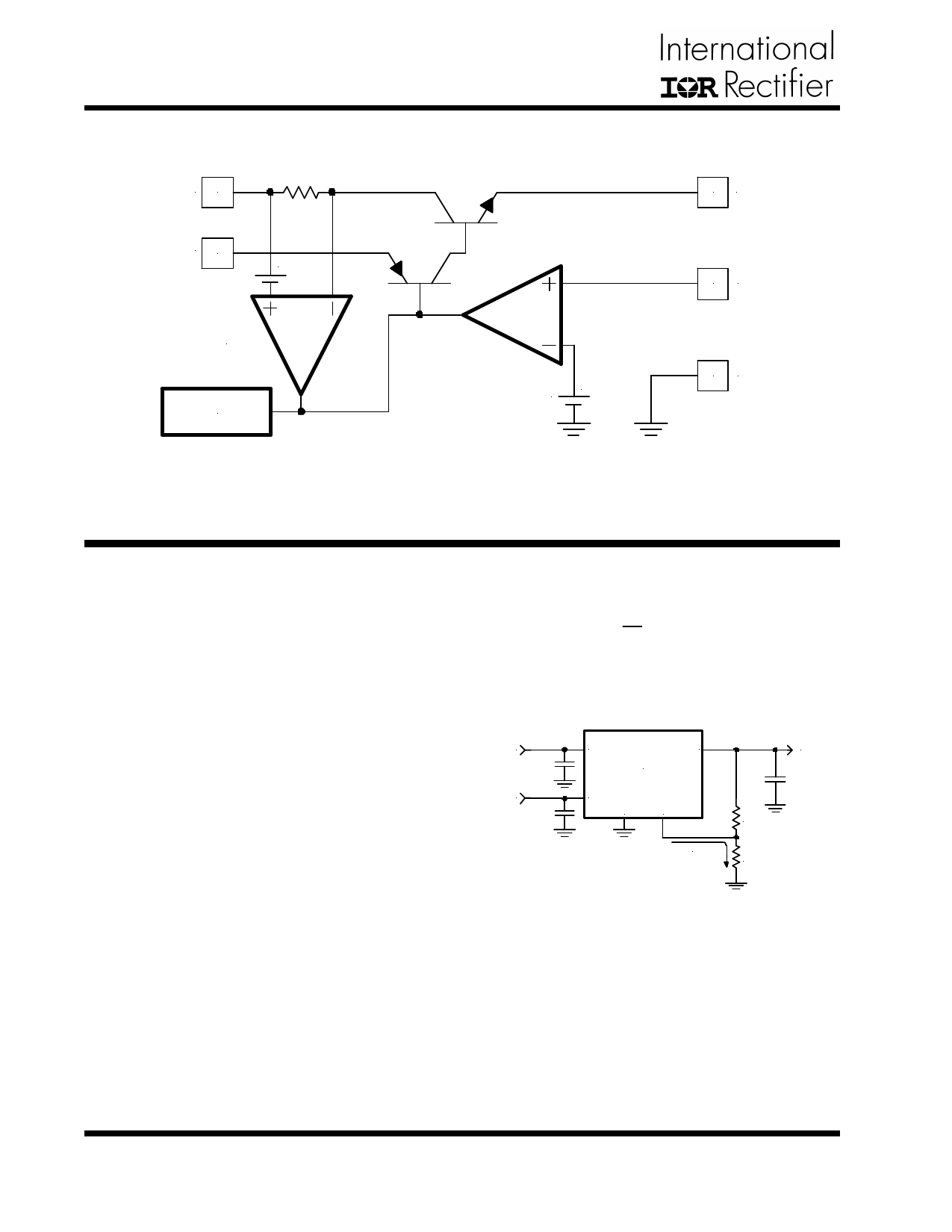
BLOCK DIAGRAM
VIN 2
VCTRL 1
+
CURRENT
LIMIT
THERMAL
SHUTDOWN
1.25V +
4 VOUT
5 VADJ
3 Gnd
Figure 2 - Simplified block diagram of the IRU1120.
APPLICATION INFORMATION
Introduction
The IRU1120 adjustable regulator is a five-terminal de-
vice designed specifically to provide extremely low drop-
out voltages comparable to the PNP type without the
disadvantage of the extra power dissipation due to the
base current associated with PNP regulators. This is
done by bringing out the control pin of the regulator that
provides the base current to the power NPN and con-
necting it to a voltage that is grater than the voltage present
at the VIN pin. This flexibility makes the IRU1120 ideal
for applications where dual inputs are available such as
a computer mother board with an ATX style power sup-
ply that provides 5V and 3.3V to the board.
The IRU1120 is specifically designed to meet the fast
current transient needs as well as providing an accurate
initial voltage, reducing the overall system cost with the
need for fewer number of output capacitors.
( )R1
VOUT = VREF3 1+ R2 +IADJ3R1
Where:
VREF = 1.25V Typically
IADJ < 1mA Typically
R1 and R2 as shown in Figure 3:
VIN
VCTRL
VIN
VOUT
IRU1120
VCTRL
Gnd Adj
R1
IADJ = 1uA
R2
VOUT
Figure 3 - Typical application of the IRU1120
for programming the output voltage.
Output Voltage Setting
The IRU1120 can be programmed to any voltage in the
range of 1.25V to 5.5V by using two external resistors.
The output voltage is defined as:
The IRU1120 keeps a constant 1.25V between the ad-
just pin and the ground pin. By replacing a resistor (R2),
between these two pins, a constant current flows through
R1, subtracting the IADJ current out of the R1 to set the
overall output voltage. Notice that since the IADJ is typi-
cally in the range of 1mA, it only adds a small error to
the output voltage which is negligible.
4
www.irf.com
Rev. 1.3
08/20/02
Share Link: 