LA75676VA Ver la hoja de datos (PDF) - SANYO -> Panasonic
Número de pieza
componentes Descripción
Lista de partido
LA75676VA Datasheet PDF : 10 Pages
| |||
LA75676VA
V14. Frequency characteristics • • • • [fc]
1. Apply a DC voltage to the external AGC IF input (pin 17) and vary that voltage.
2. SG1 : 45.75MHz, CW, 10mVrms
SG2 : from 45.65MHz to 39.75MHz, CW, 2mVrms
Add SG1 and SG2 using a T pad, adjust the signal generator levels to those listed above, and apply the result to
VIF IN.
3. First, set the SG2 frequency to 45.65MHz.
Next, adjust the IF AGC voltage (pin 17) so that the output level at test point A becomes 0.5Vp-p. • • V1
4. Set the SG2 frequency to 39.75MHz and measure the output level. • • V2
5. Perform the following calculation.
V2
fc = 20log V1 (dB)
V15, V16. Differential gain and differential phase • • • • [DG, DP]
1. Internal AGC
2. fp = 45.75MHz, APL 50%, 87.5% video signal, Vi = 10mVrms
3. Measure DG and DP at test point A.
V17. AFT voltage (no signal) • • • • V13
1. Internal AGC
2. Measure the DC voltage on the AFT output (B).
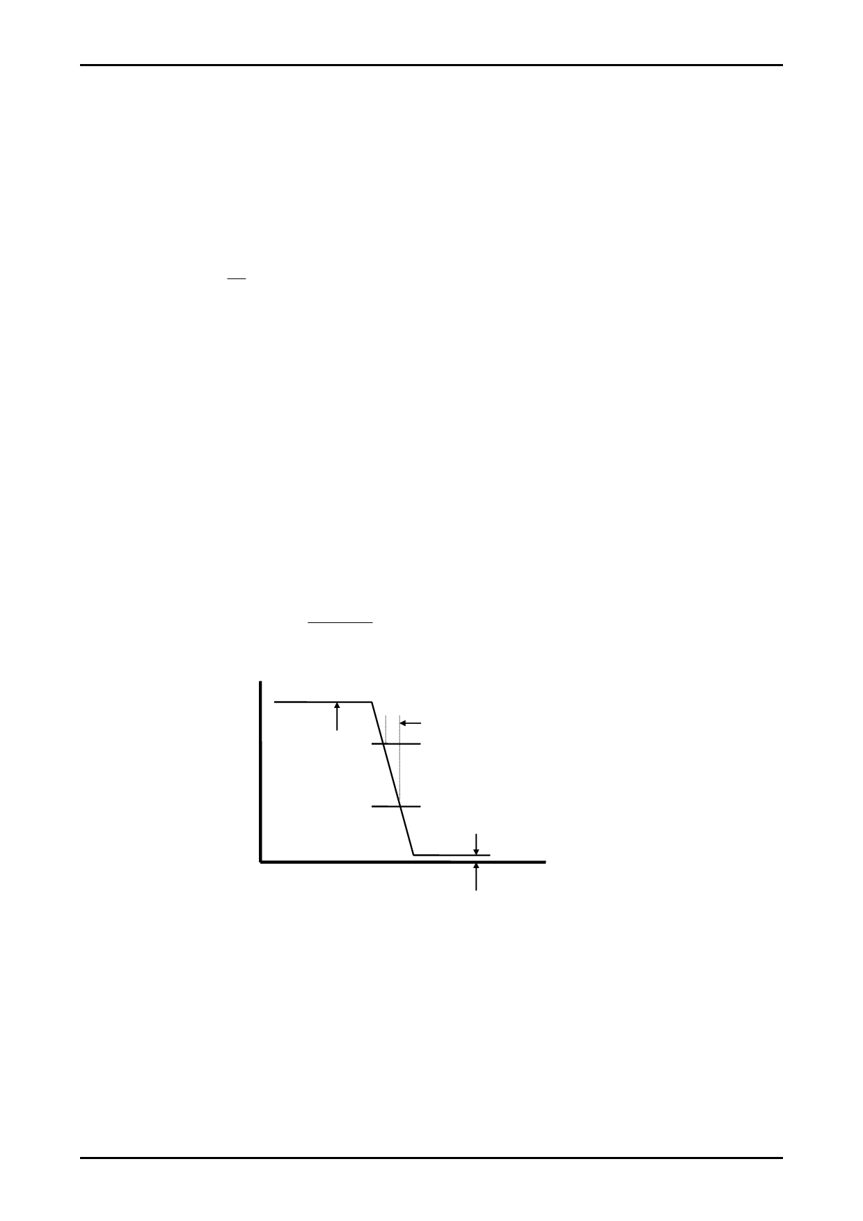
V18, V19, V20. Maximum AFT voltage, minimum AFT voltage, AFT detection sensitivity • • • • [V13H, V13L, Sf]
1. Internal AGC
2. fp = 45.75MHz, ±1.5MHz sweep, 10mVrms (VIF input)
3. Record the maximum voltage as V13H and the minimum voltage as V13L.
4. Measure the frequency shift for the change in voltage at test point B from V1 to V2. • • ∆f
Sƒ
=
2000 (mV)
∆f (kHz)
mV/kHz
AFT output
(V)
V13H
∆f
V1 ; 3.5V
V2 ; 1.5V
V13L
IF frequency (MHz)
No.7868-7/10
Share Link: 