LT3027 Ver la hoja de datos (PDF) - Linear Technology
Número de pieza
componentes Descripción
Lista de partido
LT3027
Linear Technology

LT3027 Datasheet PDF : 16 Pages
| |||
LT3027
APPLICATIO S I FOR ATIO
Output Capacitance and Transient Response
The LT3027 regulator is designed to be stable with a wide
range of output capacitors. The ESR of the output capaci-
tor affects stability, most notably with small
capacitors. A minimum output capacitor of 1µF with an
ESR of 3Ω or less is recommended to prevent oscilla-
tions. The LT3027 is a micropower device and output
transient response will be a function of output capaci-
tance. Larger values of output capacitance decrease the
peak deviations and provide improved transient response
for larger load current changes. Bypass capacitors, used
to decouple individual components powered by the
LT3027, will increase the effective output capacitor value.
With larger capacitors used to bypass the reference (for
low noise operation), larger values of output capacitors
are needed. For 100pF of bypass capacitance, 2.2µF of
output capacitor is recommended. With a 330pF bypass
capacitor or larger, a 3.3µF output capacitor is recom-
mended. The shaded region of Figure 2 defines the region
over which the LT3027 regulator is stable. The minimum
ESR needed is defined by the amount of bypass capaci-
tance used, while the maximum ESR is 3Ω.
Extra consideration must be given to the use of ceramic
capacitors. Ceramic capacitors are manufactured with a
variety of dielectrics, each with different behavior across
temperature and applied voltage. The most common
4.0
3.5
3.0
STABLE REGION
2.5
2.0
1.5 CBYP = 0
CBYP = 100pF
1.0
CBYP = 330pF
CBYP > 3300pF
0.5
0
1
2
3 4 5 6 7 8 9 10
OUTPUT CAPACITANCE (µF)
3027 F02
Figure 2. Stability
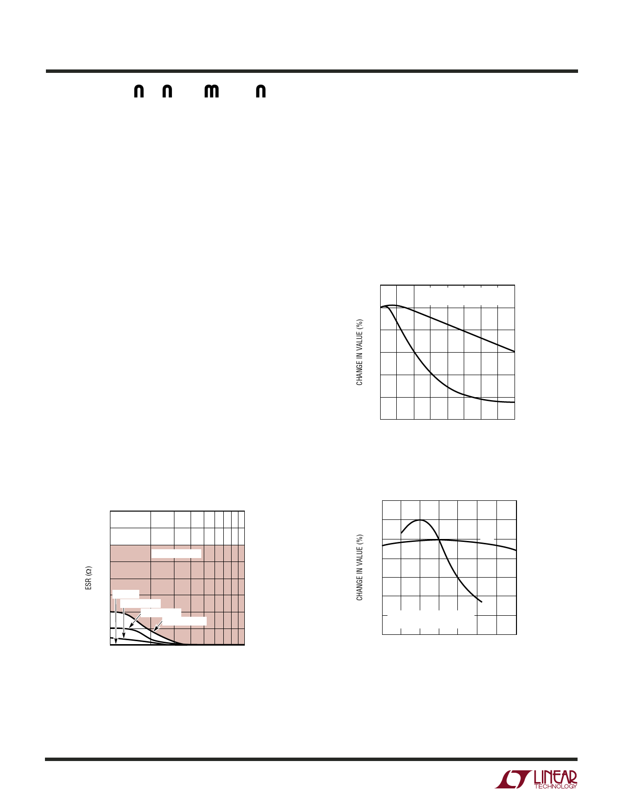
dielectrics used are Z5U, Y5V, X5R and X7R. The Z5U and
Y5V dielectrics are good for providing high capacitances
in a small package, but exhibit strong voltage and tem-
perature coefficients as shown in Figures 3 and 4. When
used with a 5V regulator, a 10µF Y5V capacitor can exhibit
an effective value as low as 1µF to 2µF over the operating
temperature range. The X5R and X7R dielectrics result in
more stable characteristics and are more suitable for use
as the output capacitor. The X7R type has better stability
across temperature, while the X5R is less expensive and
is available in higher values.
20
BOTH CAPACITORS ARE 16V,
1210 CASE SIZE, 10µF
0
X5R
–20
–40
–60
Y5V
–80
–100
0 2 4 6 8 10 12 14 16
DC BIAS VOLTAGE (V)
3027 F03
Figure 3. Ceramic Capacitor DC Bias Characteristics
40
20
0
X5R
–20
–40
Y5V
–60
–80 BOTH CAPACITORS ARE 16V,
1210 CASE SIZE, 10µF
–100
–50 –25 0 25 50 75
TEMPERATURE (°C)
100 125
3027 F04
Figure 4. Ceramic Capacitor Temperature Characteristics
3027f
10
Share Link: