LT3080 Ver la hoja de datos (PDF) - Linear Technology
Número de pieza
componentes Descripción
Lista de partido
LT3080 Datasheet PDF : 26 Pages
| |||
LT3080
APPLICATIONS INFORMATION
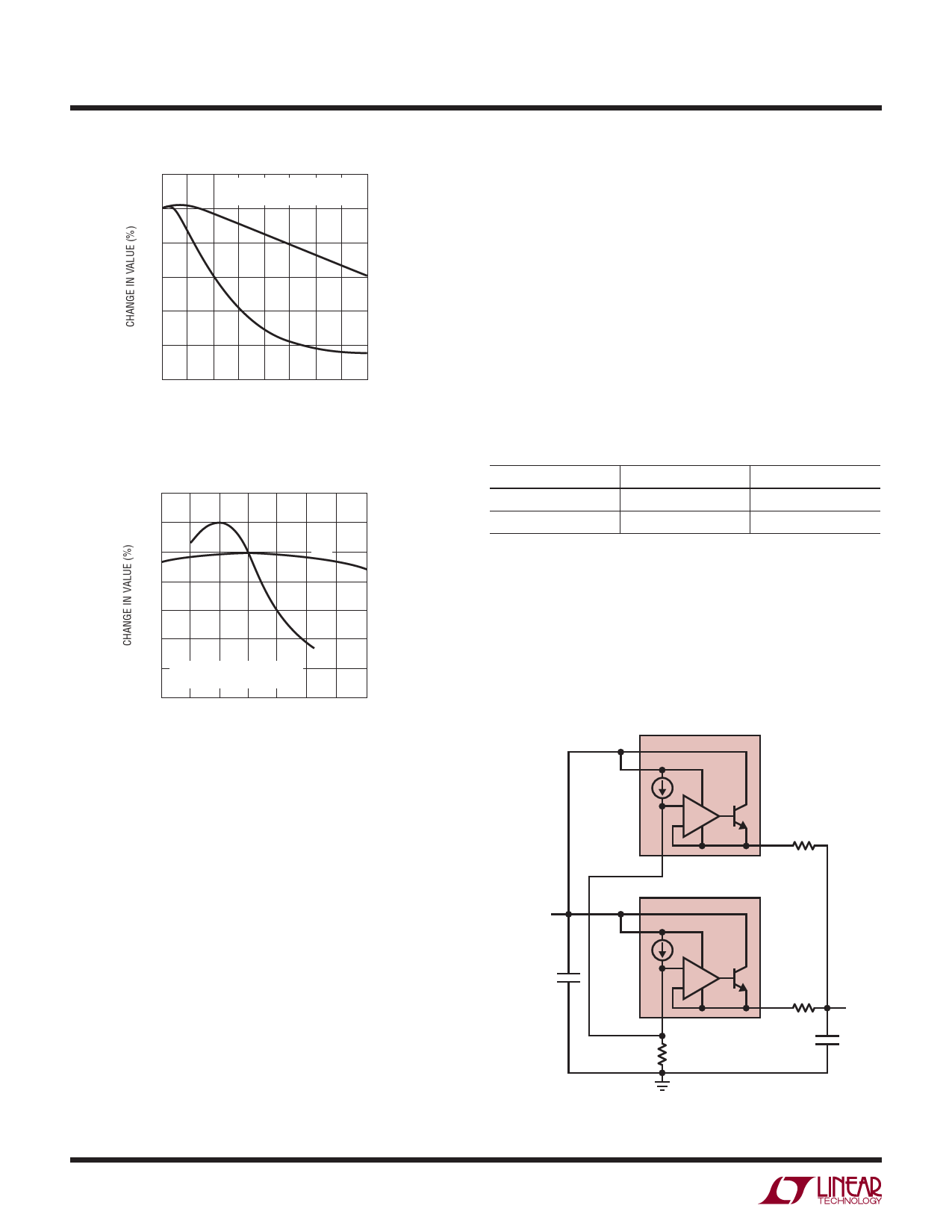
20
BOTH CAPACITORS ARE 16V,
1210 CASE SIZE, 10μF
0
X5R
–20
–40
–60
Y5V
–80
–100
0 2 4 6 8 10 12 14 16
DC BIAS VOLTAGE (V)
3080 F02
Figure 2. Ceramic Capacitor DC Bias Characteristics
40
20
0
X5R
–20
–40
Y5V
–60
–80 BOTH CAPACITORS ARE 16V,
1210 CASE SIZE, 10μF
–100
–50 –25 0 25 50 75
TEMPERATURE (°C)
100 125
3080 F03
Figure 3. Ceramic Capacitor Temperature Characteristics
available in higher values. Care still must be exercised when
using X5R and X7R capacitors; the X5R and X7R codes
only specify operating temperature range and maximum
capacitance change over temperature. Capacitance change
due to DC bias with X5R and X7R capacitors is better than
Y5V and Z5U capacitors, but can still be significant enough
to drop capacitor values below appropriate levels. Capaci-
tor DC bias characteristics tend to improve as component
case size increases, but expected capacitance at operating
voltage should be verified.
Voltage and temperature coefficients are not the only
sources of problems. Some ceramic capacitors have a
piezoelectric response. A piezoelectric device generates
voltage across its terminals due to mechanical stress,
similar to the way a piezoelectric microphone works. For a
10
ceramic capacitor the stress can be induced by vibrations
in the system or thermal transients.
Paralleling Devices
LT3080’s may be paralleled to obtain higher output current.
The SET pins are tied together and the IN pins are tied
together. This is the same whether it’s in three terminal
mode or has separate input supplies. The outputs are
connected in common using a small piece of PC trace
as a ballast resistor to equalize the currents. PC trace
resistance in milliohms/inch is shown in Table 1. Only a
tiny area is needed for ballasting.
Table 1. PC Board Trace Resistance
WEIGHT (oz)
10 mil WIDTH
1
54.3
2
27.1
Trace resistance is measured in mOhms/in
20 mil WIDTH
27.1
13.6
The worse case offset between the set pin and the output
of only ± 2 millivolts allows very small ballast resistors
to be used. As shown in Figure 4, the two devices have
a small 10 milliohm ballast resistor, which at full output
current gives better than 80 percent equalized sharing
of the current. The external resistance of 10 milliohms
VIN
4.8V TO 28V
1μF
VIN
VCONTROL
LT3080
+
–
SET
OUT 10mΩ
VIN
VCONTROL
LT3080
+
–
SET
165k
OUT 10mΩ
VOUT
3.3V
2A
10μF
3080 F04
Figure 4. Parallel Devices
3080fb
Share Link: 