LT138A Ver la hoja de datos (PDF) - Linear Technology
Número de pieza
componentes Descripción
Lista de partido
LT138A Datasheet PDF : 12 Pages
| |||
APPLICATIONS INFORMATION
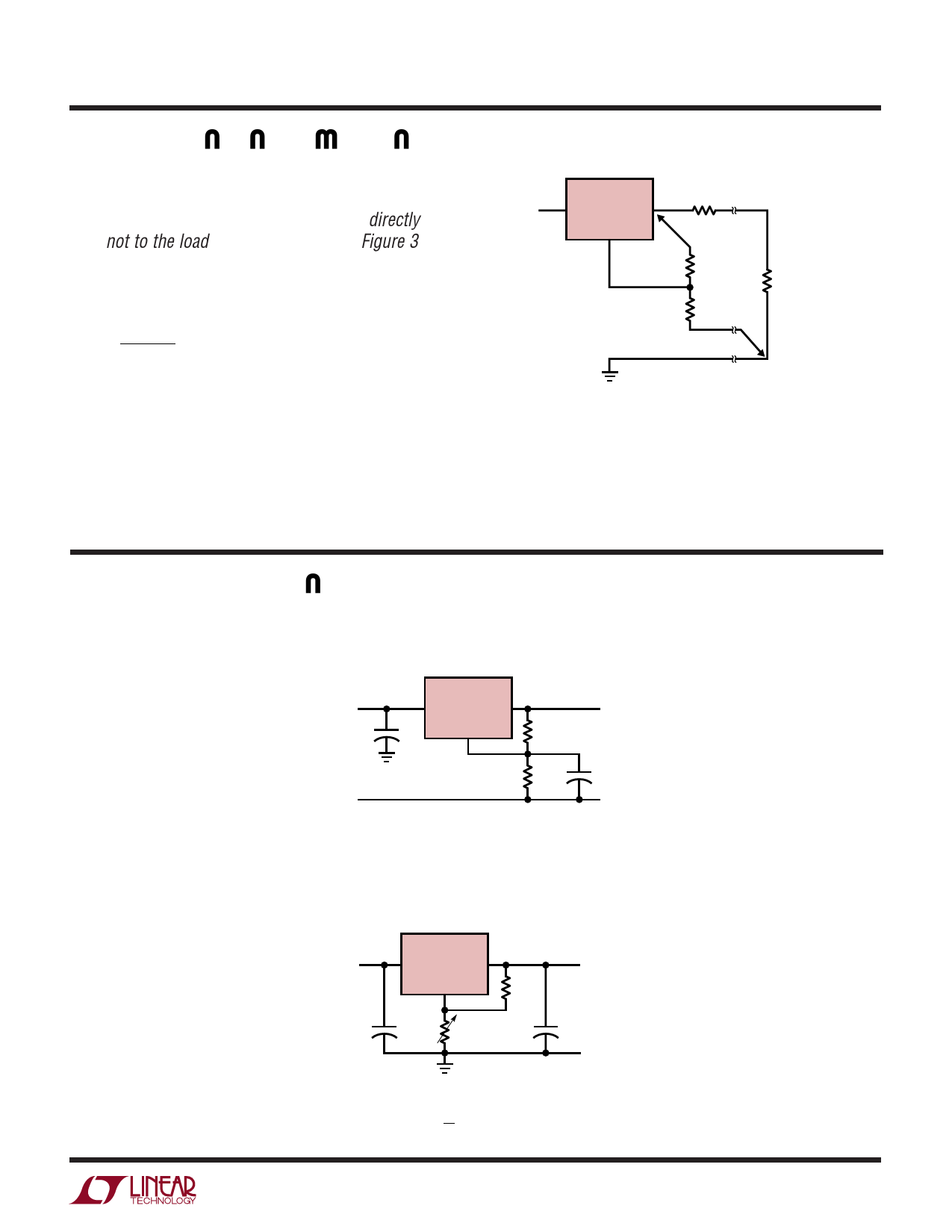
negative side of the load. Although it may not be immedi-
ately obvious, best load regulation is obtained when the
top of the resistor divider, R1, is connected directly to the
case not to the load. This is illustrated in Figure 3. If R1
were connected to the load, the effective resistance be-
tween the regulator and the load would be:
RP
R2 + R1
R1
,
RP
=
Parasitic
Line
Re sistance
Connected as shown, RP is not multiplied by the divider
ratio. RP is about 0.004Ω per foot using 16 gauge wire.
This translates to 4mV/ft at 1A load current, so it is
important to keep the positive lead between regulator and
load as short as possible, and use large wire or PC board
traces.
LT138A/LT338A
LM138/LM338
LT338A
RP
PARASITIC
LINE RESISTANCE
VIN
VIN
VOUT
ADJ
CONNECT
R1 TO CASE
R1
RL
R2
CONNECT
R2 TO LOAD
138A/338A F03
Figure 3. Connections for Best Load Regulation
TYPICAL APPLICATIONS
Improving Ripple Rejection
LT338A
VIN
+
VIN
1µF
VOUT
ADJ
R1
121Ω
1%
R2 +
365Ω
1%
5V
CL*
10µF
*C1 IMPROVES RIPPLE REJECTION, XC
SHOULD BE SMALL COMPARED TO R2
138A/338A TA03
1.2V to 25V Adjustable Regulator
LT338A
VIN
VIN
VOUT
ADJ
+
C1*
R2
1µF
5k
R1
240Ω
+
VOUT†
C2**
1µF
138A/338A TA04
*NEEDED IF DEVICE IS FAR FROM FILTER CAPACITORS
**OPTIONAL, IMPROVES TRANSIENT RESPONSE
( ) †VOUT = 1.25V
1 + R2
R1
138afb
7
Share Link: 