MAX608ESA Ver la hoja de datos (PDF) - Maxim Integrated
Número de pieza
componentes Descripción
Lista de partido
MAX608ESA Datasheet PDF : 12 Pages
| |||
5V or Adjustable, Low-Voltage,
Step-Up DC-DC Controller
Unlike traditional PFM converters, the MAX608 uses a
sense resistor to control the peak inductor current. The
device also operates with high switching frequencies
(up to 300kHz), allowing the use of miniature external
components.
As with traditional PFM converters, the power transistor
is not turned on until the voltage comparator senses
the output is out of regulation. However, unlike tradition-
al PFM converters, the MAX608 switch uses the combi-
nation of a peak current limit and a pair of one-shots
that set the maximum on-time (16µs) and minimum off-
time (2.3µs); there is no oscillator. Once off, the mini-
mum off-time one-shot holds the switch off for 2.3µs.
After this minimum time, the switch either 1) stays off if
the output is in regulation, or 2) turns on again if the
output is out of regulation.
The control circuitry allows the IC to operate in continu-
ous-conduction mode (CCM) while maintaining high
efficiency with heavy loads. When the power switch is
turned on, it stays on until either 1) the maximum on-
time one-shot turns it off (typically 16µs later), or 2) the
switch current reaches the peak current limit set by the
current-sense resistor.
The MAX608 switching frequency is variable (depend-
ing on load current and input voltage), causing variable
switching noise. However, the subharmonic noise gen-
erated does not exceed the peak current limit times the
filter capacitor equivalent series resistance (ESR). For
example, when generating a 5V output at 500mA from
a 2V input, only 75mV of output ripple occurs, using the
circuit of Figure 2a.
Low-Voltage Start-Up Oscillator
The MAX608 features a low input voltage start-up oscil-
lator that guarantees start-up with no load for input volt-
ages down to 1.8V. At these low voltages, the output
voltage is not large enough for proper error-comparator
operation and internal biasing. The start-up oscillator
has a fixed 50% duty cycle and the MAX608 disregards
the error-comparator output when the output voltage is
less than 2.5V. Above 2.5V, the error-comparator and
normal one-shot timing circuitry are used.
Shutdown Mode
When SHDN is high, the MAX608 enters shutdown
mode. In this mode, the internal biasing circuitry is
turned off (including the reference), and VOUT falls to
a diode drop below VIN (due to the DC path from the
input to the output). In shutdown mode, the supply
current drops to less than 5µA. SHDN is a TTL/CMOS
logic-level input. Connect SHDN to GND for normal
operation.
FB
MAX608
R2
VOUT
R1
C5*
R1 = 10k TO 500k
GND
( ) R2 = R1 VOUT -1
VREF
VREF = 1.5V
* OPTIONAL, SEE TEXT FOR VALUE
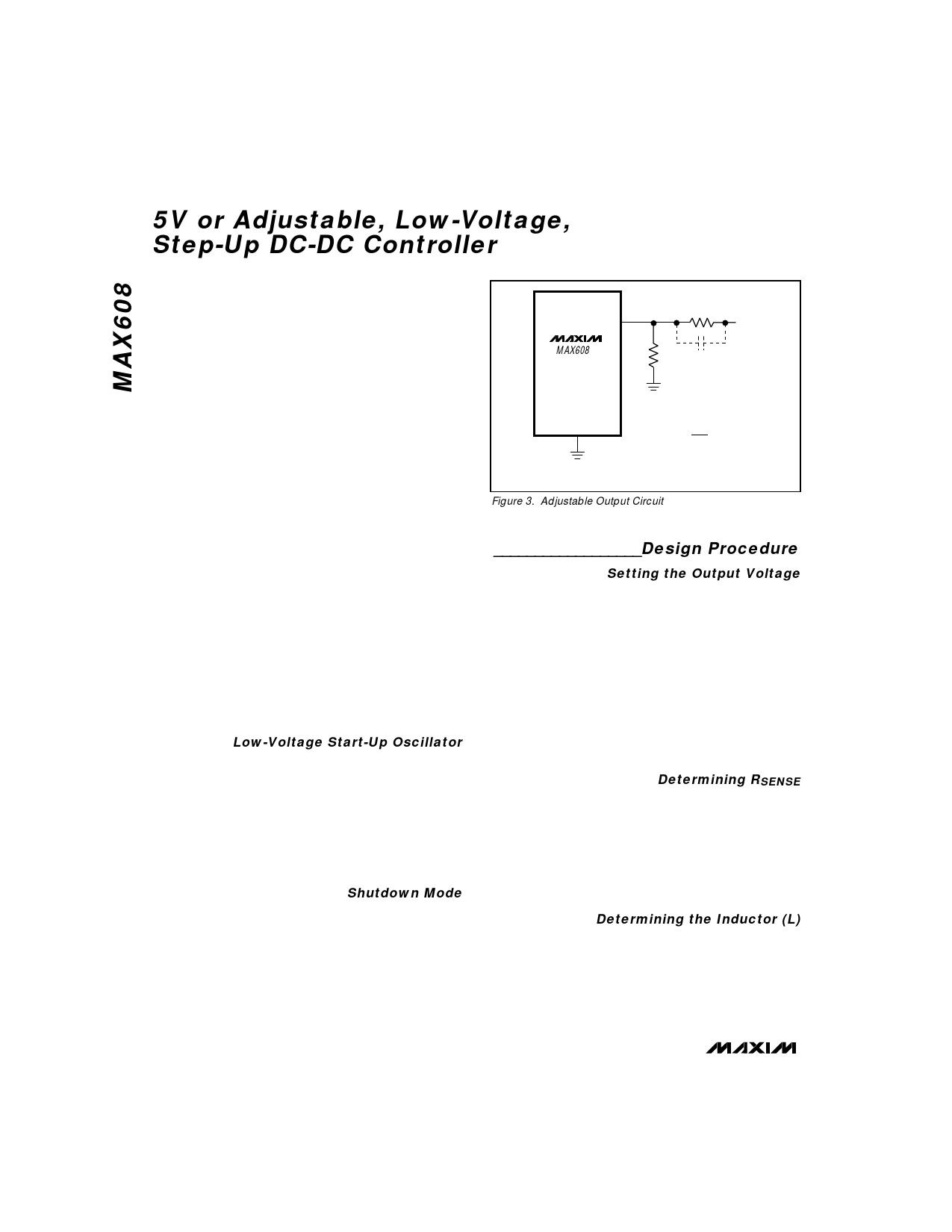
Figure 3. Adjustable Output Circuit
__________________Design Procedure
Setting the Output Voltage
The MAX608’s output voltage is preset to 5V (FB = 0V),
or it can be adjusted from 16.5V down to 3V using exter-
nal resistors R1 and R2, configured as shown in Figure 3.
For adjustable-output operation, select feedback resistor
R1 in the 10kΩ to 500kΩ range. R2 is given by:
( ) R2 = (R1) –V–O–U––T -1
VREF
where VREF equals 1.5V.
OUT must always be connected to the circuit output.
Figure 2 shows various circuit configurations for preset/
adjustable operation.
Determining RSENSE
Use the theoretical output current curves shown in
Figures 4a–4d to select RSENSE. They are derived
using the minimum (worst-case) current-limit compara-
tor threshold value over the extended temperature
range (-40°C to +85°C). No tolerance was included for
RSENSE. The voltage drop across the diode is assumed
to be 0.5V, and the drop across the power switch
rDS(ON) and coil resistance is assumed to be 0.3V.
Determining the Inductor (L)
Practical inductor values range from 10µH to 300µH.
22µH is a good choice for most applications. In appli-
cations with large input/output differentials, the IC’s out-
put-current capability will be much less when the induc-
tance value is too low, because the IC will always operate
in discontinuous mode. If the inductor value is too low, the
8 _______________________________________________________________________________________
Share Link: 