MAX1484EUB Ver la hoja de datos (PDF) - Maxim Integrated
Número de pieza
componentes Descripción
Lista de partido
MAX1484EUB Datasheet PDF : 16 Pages
| |||
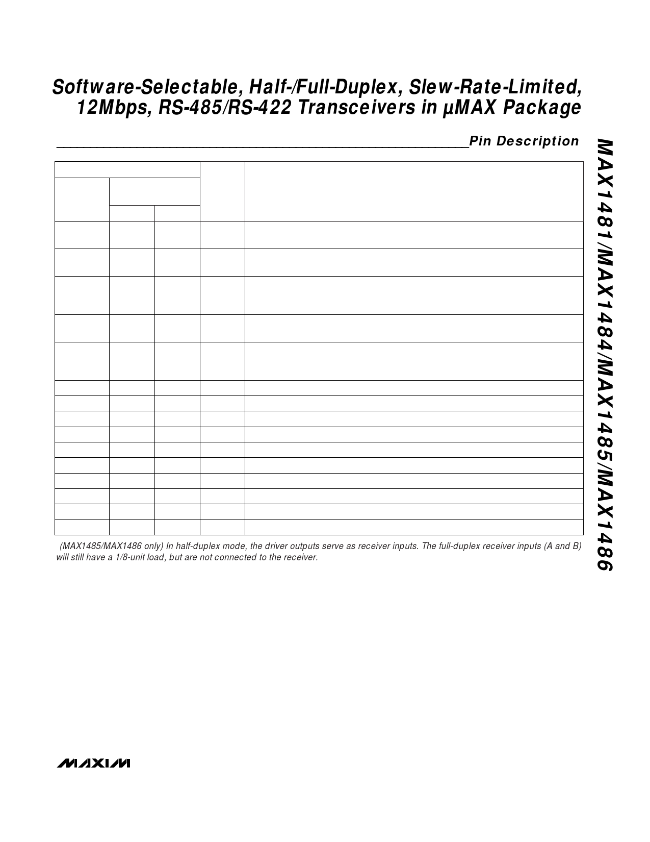
Software-Selectable, Half-/Full-Duplex, Slew-Rate-Limited,
12Mbps, RS-485/RS-422 Transceivers in µMAX Package
______________________________________________________________Pin Description
PIN PIN
MAX1481/
MAX1484
MAX1485/MAX1486
H/F = 0 H/F = 1
NAME
1
1
1
RO
—
2
2
H/F
2
—
—
RE
3
3
3
DE
FUNCTION
Receiver Output. When RE is low and if A - B ≥ 200mV, RO goes high; if A - B ≤
-200mV, RO goes low.
Half-/Full-Duplex Selector Input. Connect H/F to VCC for half-duplex mode, and
connect to GND for full-duplex mode.
Receiver Output Enable Input. Drive RE low to enable RO; RO is high impedance
when RE is high. For MAX1481 only, drive RE high and DE low to enter the low-
power shutdown mode.
Driver Output Enable Input. Drive DE high to enable driver outputs. These outputs
are high impedance when DE is low.
Driver Input. With DE high, a low on DI forces noninverting output low and invert-
4
4
4
DI
ing output high. Similarly, a high on DI forces noninverting output high and invert-
ing output low.
5
5
5
GND Ground
6
6
—
B
Inverting Receiver Input
—
—
6
B
Receiver Input Resistors*
7
7
—
Z
Inverting Driver Output
—
—
7
Z
Inverting Driver Output and Inverting Receiver Input
8
8
—
Y
Noninverting Driver Output
—
—
8
Y
Noninverting Driver Output and Noninverting Receiver Input
9
9
—
A
Noninverting Receiver Input
—
—
9
A
Receiver Input Resistors*
10
10
10
VCC
Positive Supply; +4.75V ≤ VCC ≤ +5.25V
*(MAX1485/MAX1486 only) In half-duplex mode, the driver outputs serve as receiver inputs. The full-duplex receiver inputs (A and B)
will still have a 1/8-unit load, but are not connected to the receiver.
_______________________________________________________________________________________ 7
Share Link: 