MAX7432AEUD Ver la hoja de datos (PDF) - Maxim Integrated
Número de pieza
componentes Descripción
Lista de partido
MAX7432AEUD Datasheet PDF : 21 Pages
| |||
Standard Definition Video Reconstruction
Filters and Buffers
ABSOLUTE MAXIMUM RATINGS
VCC to GND ...........................................................................+6V
All Other Pins to GND .................................-0.3V to (VCC + 0.3V)
Maximum Current Into Any Pin .........................................±50mA
Continuous Power Dissipation (TA = +70°C)
8-Pin SOT23 (derate 9.71mW/°C above +70°C)..........777mW
10-Pin µMAX (derate 6.94mW/°C above +70°C) ......555.5mW
14-Pin TSSOP (derate 9.1mW/°C above +70°C) .........727mW
Operating Temperature Range ...........................-40°C to +85°C
Storage Temperature Range .............................-65°C to +150°C
Junction Temperature ......................................................+150°C
Lead Temperature (soldering, 10s) .................................+300°C
Stresses beyond those listed under “Absolute Maximum Ratings” may cause permanent damage to the device. These are stress ratings only, and functional
operation of the device at these or any other conditions beyond those indicated in the operational sections of the specifications is not implied. Exposure to
absolute maximum rating conditions for extended periods may affect device reliability.
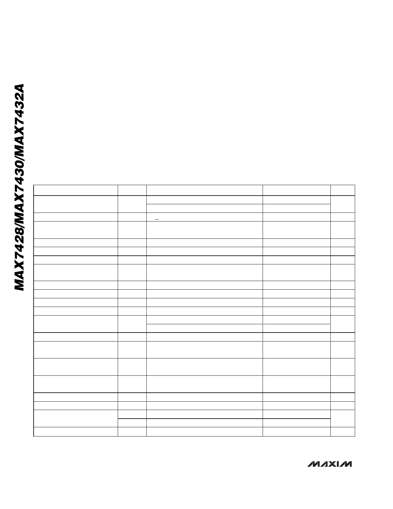
ELECTRICAL CHARACTERISTICS
(VCC = +5V ±10%, RREXT = 300kΩ ±1%, CIN = 0.1µF, CREXT = (1nF to 1µF) ±1%, CLOAD = 0 to 20pF; BOOST0_, BOOST1_ = 0, 0;
TA = TMIN to TMAX, unless otherwise noted. Typical values are at TA = +25°C.) (Note 2)
PARAMETER
Passband Response
Stopband Attenuation
HF Boost Relative Step Size, 4
Levels
Differential Gain
Differential Phase
Harmonic Distortion
Signal-to-Noise Ratio
Group Delay Deviation
Line-Time Distortion
Field-Time Distortion
Clamp Settling Time
Output DC Clamp Level
Low-Frequency Gain
Group Delay Matching
SYMBOL
Asb
CONDITIONS
f = 100kHz to 4.2MHz relative to 100kHz
f = 100kHz to 5MHz relative to 100kHz
f > 27MHz
MIN TYP MAX UNITS
-0.5
+0.5
dB
-1.0
+1.0
48
dB
f = 4.2MHz to 5MHz
0.2
0.4
0.6
dB
dG
5-step modulated staircase
0.2
%
dθ
5-step modulated staircase
0.2
degrees
THD f = 100kHz to 5MHz
0.1
0.5
%
SNR
Peak signal (2Vp-p) to RMS noise,
f = 100Hz to 50MHz
72
dB
Δtg
Deviation from 100kHz to 3.58 (4.43)MHz
Hdist 18µs, 100 IRE bar
Vdist 130 lines, 18µs, 100 IRE bar
tclamp to ±1% (Note 1)
CLEVEL = 0
0.8
CLEVEL = 1
1.35
20
ns
0.3
%
0.5
%
100 Lines
1.3
V
1.85
AV
Gain at 100kHz
1.9 1.975 2.05
V/V
tg(MATCH) Low frequency channel-to-channel matching
2
ns
f = 100kHz
Low-Frequency Gain Matching AV(MATCH) Channel-to-channel gain matching, f = 100kHz
5
%
Channel-to-Channel Crosstalk
Output Short-Circuit Current
Input Leakage Current
Input Dynamic Swing
VCC Supply Range
XTALK
ISC
IIN
YINp-p
CINp-p
VCC
Channel-to-channel crosstalk, f = 100kHz
to 5.5MHz
OUT_ shorted to ground or VCC
CLEVEL = 0
CLEVEL = 1
-60
dB
50
mA
10
µA
1.4
Vp-p
0.9
4.5
5.5
V
2 _______________________________________________________________________________________
Share Link: 