MAX845 Ver la hoja de datos (PDF) - Maxim Integrated
Número de pieza
componentes Descripción
Lista de partido
MAX845 Datasheet PDF : 16 Pages
| |||
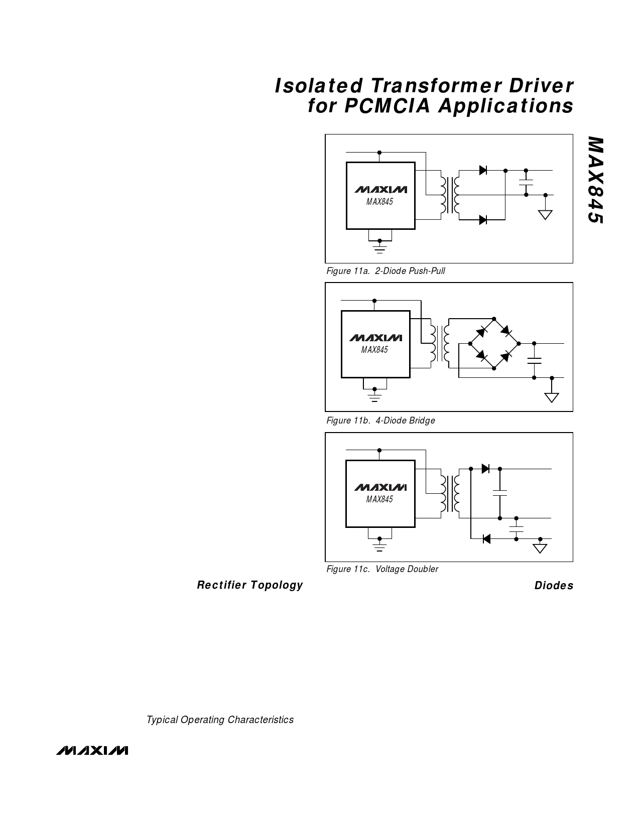
Isolated Transformer Driver
for PCMCIA Applications
2) Use a test winding to measure ET product (if using
an ungapped toroid) and/or AL value for the core.
3) Determine the number of turns required for the pri-
mary winding. For an ungapped toroid, ET product
from center-tap to D1 must be at least 5V-µs. Other
core types must have sufficient inductance to limit
D1 and D2 output current under minimum load con-
ditions, and must not be allowed to saturate.
4) Select a rectifier topology based on performance
requirements (ripple vs. loss, and space required
for secondary winding). Refer to Table 2, Rectifier
Topology Trade-Offs.
5) Work backward from VOUT requirements to deter-
mine the secondary to primary turns ratio. Include
losses in the rectifier diodes, and estimate resistive
losses in the windings. For load currents exceed-
ing 150mA, use a voltage step-down transformer to
step up the output current from the MAX845. Do
not exceed the MAX845’s absolute maximum out-
put current rating (200mA).
6) Wind the transformer with the largest diameter wire
that will fit the winding area. Select a wire gauge to
fill the winding aperture as much as possible.
Larger diameter wire has lower resistance per unit
length. Doubling the wire diameter reduces resis-
tive losses by a factor of four.
Bobbin or drum cores suffer from low coupling between
windings. This usually requires bifilar winding for the
two halves of the primary.
Due to the inherent complexity of magnetic circuit
design, it will be necessary to build a prototype and re-
iterate the design. If necessary, adjust the design by
altering the number of primary or secondary turns, or the
wire gauge. If using a different core material or geome-
try, evaluate its ET product or AL as described above.
Rectifier Topology
Figure 11 shows various rectifier topologies. Refer to
Table 2 for selection criteria. The turns ratio of the trans-
former must be set to provide the minimum required out-
put voltage at the maximum anticipated load, with the
minimum expected input voltage. In addition, the calcu-
lations should allow for worst-case losses in the recti-
fiers. Since the turns ratio determined in this manner will
ordinarily produce a much higher voltage at the sec-
ondary under conditions of high input voltage and/or
light loading, be careful to prevent an overvoltage con-
dition from occurring (see the Output Voltage vs. Load
Current graph in the Typical Operating Characteristics).
VIN
6
VCC
1
D1
MAX845
8
GND1 GND2 D2
2
7
Figure 11a. 2-Diode Push-Pull
VIN
6
VCC
1
D1
MAX845
8
GND1 GND2 D2
2
7
Figure 11b. 4-Diode Bridge
VIN
6
VCC
D1 1
MAX845
GND1 GND2 D2 8
2
7
Figure 11c. Voltage Doubler
Diodes
Use fast-switching diode rectifiers. Ordinary silicon sig-
nal diodes like the 1N914 or 1N4148 may be used for
low output current levels (less than 50mA), but Schottky
diodes have a lower forward voltage drop and should
be used for higher-current applications. Central
Semiconductor has low-current Schottky diodes as
duals in SOT-23 packages (CMPSH-3 series). The
Nihon SB05W05C is a common-cathode dual in a SOT-
23; it works well in the two-diode full-wave configura-
tion. The Motorola MBR0520 is an excellent choice for
all configurations.
______________________________________________________________________________________ 13
Share Link: 