MC14541B(2000) Ver la hoja de datos (PDF) - ON Semiconductor
Número de pieza
componentes Descripción
Lista de partido
MC14541B Datasheet PDF : 8 Pages
| |||
MC14541B
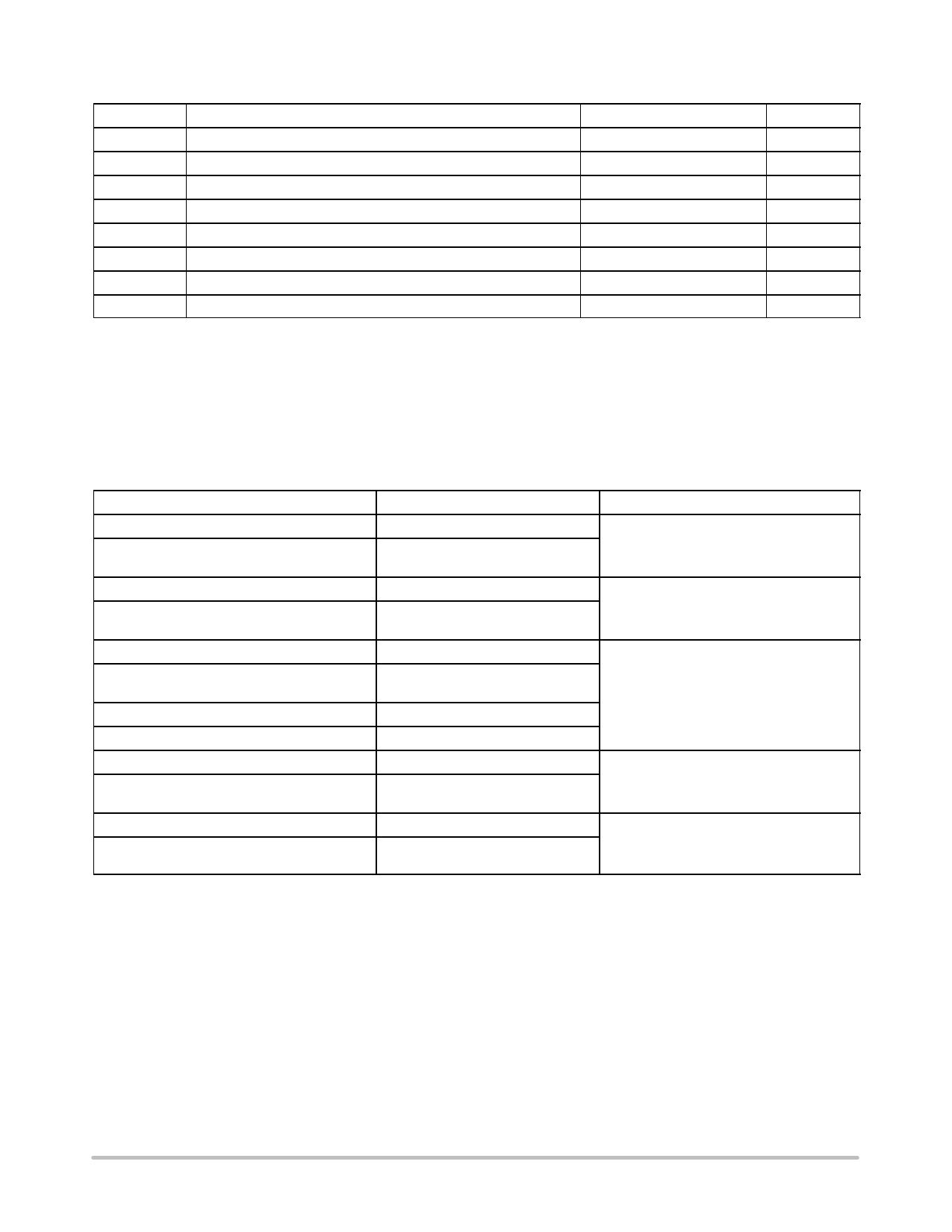
PIN ASSIGNMENT
Rtc 1
Ctc 2
RS 3
NC 4
AR 5
MR 6
VSS 7
14 VDD
13 B
12 A
11 NC
10 MODE
9 Q/Q SEL
8Q
NC = NO CONNECTION
ÎÎÎÎÎÎÎÎÎÎÎÎÎÎÎÎÎÎÎÎÎÎÎÎÎÎÎÎÎÎÎÎÎ ELECTRICAL CHARACTERISTICS (Voltages Referenced to VSS)
VDD
– 55_C
25_C
125_C
Characteristic
Symbol Vdc
Min
Max
Min Typ (4.) Max
Min
Max Unit
Output Voltage
Vin = VDD or 0
“0” Level VOL
5.0
10
15
—
0.05
—
—
0.05
—
—
0.05
—
0
0.05
—
0.05 Vdc
0
0.05
—
0.05
0
0.05
—
0.05
Vin = 0 or VDD
“1” Level VOH
5.0
4.95
—
4.95
5.0
10
9.95
—
9.95
10
15
14.95
—
14.95
15
—
4.95
—
Vdc
—
9.95
—
—
14.95
—
Input Voltage
“0” Level VIL
(VO = 4.5 or 0.5 Vdc)
(VO = 9.0 or 1.0 Vdc)
(VO = 13.5 or 1.5 Vdc)
“1” Level VIH
(VO = 0.5 or 4.5 Vdc)
(VO = 1.0 or 9.0 Vdc)
(VO = 1.5 or 13.5 Vdc)
Output Drive Current
(VOH = 2.5 Vdc)
(VOH = 9.5 Vdc)
(VOH = 13.5 Vdc)
IOH
Source
(VOL = 0.4 Vdc)
(VOL = 0.5 Vdc)
(VOL = 1.5 Vdc)
Sink IOL
Input Current
Iin
Input Capacitance
Cin
(Vin = 0)
Quiescent Current
IDD
(Pin 5 is High)
Auto Reset Disabled
5.0
—
1.5
—
10
—
3.0
—
15
—
4.0
—
2.25
4.50
6.75
Vdc
1.5
—
1.5
3.0
—
3.0
4.0
—
4.0
5.0
3.5
—
3.5
2.75
10
7.0
—
7.0
5.50
15
11
—
11
8.25
Vdc
—
3.5
—
—
7.0
—
—
11
—
5.0 – 7.96 — – 6.42 – 12.83
10 – 4.19 — – 3.38 – 6.75
15 – 16.3 — – 13.2 – 26.33
mAdc
— – 4.49 —
— – 2.37 —
— – 9.24 —
5.0
1.93
—
1.56
3.12
10
4.96
—
4.0
8.0
15
19.3
—
15.6
31.2
—
1.09
— mAdc
—
2.8
—
—
10.9
—
15
—
± 0.1
— ± 0.00001 ± 0.1
—
± 1.0 µAdc
—
—
—
—
5.0
7.5
—
—
pF
5.0
—
5.0
—
0.005
5.0
—
150 µAdc
10
—
10
—
0.010
10
—
300
15
—
20
—
0.015
20
—
600
Auto Reset Quiescent Current
(Pin 5 is low)
IDDR
10
15
—
250
—
—
500
—
30
250
—
1500 µAdc
82
500
—
2000
Supply Current (5.) (6.)
(Dynamic plus Quiescent)
ID
5.0
10
15
ID = (0.4 µA/kHz) f + IDD
ID = (0.8 µA/kHz) f + IDD
ID = (1.2 µA/kHz) f + IDD
µAdc
4. Data labelled “Typ” is not to be used for design purposes but is intended as an indication of the IC’s potential performance.
5. The formulas given are for the typical characteristics only at 25_C.
6. When using the on chip oscillator the total supply current (in µAdc) becomes: IT = ID + 2 Ctc VDD f x 10–3 where ID is in µA, Ctc is in pF,
VDD in Volts DC, and f in kHz. (see Fig. 3) Dissipation during power–on with automatic reset enabled is typically 50 µA @ VDD = 10 Vdc.
http://onsemi.com
2
Share Link: 