MC33215 Ver la hoja de datos (PDF) - Motorola => Freescale
Número de pieza
componentes Descripción
Lista de partido
MC33215 Datasheet PDF : 20 Pages
| |||
0.5 VLS
0
–0.5 VLS
Freescale SMeCm3i3c2o15nductor, Inc.
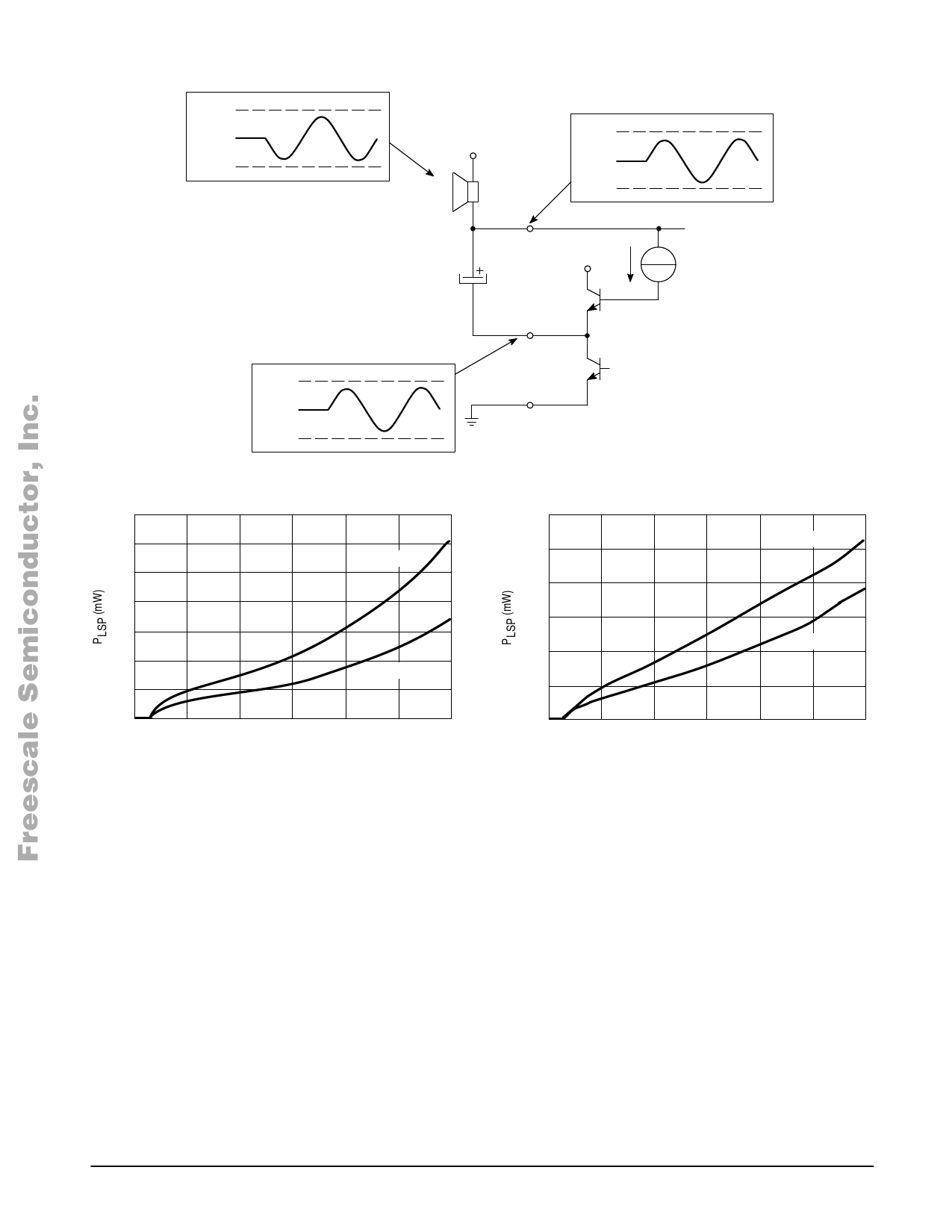
Figure 9. Loudspeaker Output Stage
VLS
Loudspeaker
1.5 VLS
VLS
0.5 VLS
CLSO
LSB
VLS
T2
VLS
0.5 VLS
0
LSO
T1
PGD
Figure 10. Loudspeaker Amplifier Output Power with External Supply
140
300
120
RLSP = 25 Ω
250
100
200
80
150
60
100
40
RLSP = 50 Ω
20
50
RLSP = 25 Ω
RLSP = 50 Ω
0
2.0
3.0
4.0
5.0
6.0
7.0
8.0
VLS (V)
A. Peak–to–Peak Limiter Active
0
2.0
3.0
4.0
5.0
6.0
7.0
8.0
VLS (V)
B. Peak–to–Peak Limiter Disabled
The total gain from the telephone line to the loudspeaker
output includes, besides the loudspeaker amplifier gain, also
the attenuation of the sidetone network and the internal gain
from RXI to RLS. When in receive mode, see under duplex
controller, the gain from RXI to RLS is maximum and equals
24 dB at maximum volume setting. The attenuation of the
sidetone network in the typical application equals 24.6 dB
which makes an overall gain from line to loudspeaker of
25.4 dB. Due to the influence of the line length AGC on the Rx
amplifier, the gain will be reduced for higher line currents.
The output stage of the MC33215 is a modified all NPN
bootstrap stage which ensures maximum output swing under
all supply conditions. The major advantage of this type of
output stage over a standard rail–to–rail output is the higher
stability. The principle of the bootstrap output stage is
explained with the aid of Figure 9.
The output LSO is biased at half the supply VLS while the
filtering of the loudspeaker with the big capacitor CLSO
requires that LSB is biased at VLS. In fact, because of the
filtering, LSB is kept at VLS/2 above the LSO output even if
LSO contains an ac signal. This allows the output transistor
T2 to be supplied for output signals with positive excursions
up to VLS without distorting the output signal. The resulting
ac signal over the loudspeaker will equal the signal at LSO.
As an indication of the high performance of this type of
amplifier, in Figure 10, the output power of the loudspeaker
amplifier as a function of supply voltage is depicted for 25 Ω
and 50 Ω loads with both the peak–to–peak limiter active and
disabled. As can be seen, in case the peak–to–peak limiter is
disabled, the output power is roughly increased with 6.0 dB,
this at the cost of increased distortion levels up to 30%.
In a telephone line powered application, the loudspeaker
amplifier output power is limited not only by the supply
voltage but also by the telephone line current. This means
that in telephones the use of 25 Ω or 50 Ω speakers is
preferred over the use of the cheaper 8.0 Ω types. Figure 11
gives the output power into the loudspeaker for a line
powered application and two different dc settings with the
peak–to–peak limiter active. In case the peak–to–peak limiter
is disabled the output power will be increased for the higher
line currents up to 6.0 dB.
MOTOROLA ANALOG IC DEVICEFDoArTAMore Information On This Product,
13
Go to: www.freescale.com
Share Link: 