MC33215 Ver la hoja de datos (PDF) - Motorola => Freescale
Número de pieza
componentes Descripción
Lista de partido
MC33215 Datasheet PDF : 20 Pages
| |||
Freescale SMeCm3i3c2o15nductor, Inc.
DESCRIPTION OF THE CIRCUIT
Based on the typical application circuit as given in
Figure 18, the MC33215 will be described in three parts: line
driver and supplies, handset operation, and handsfree
operation. The data used refer to typical data of the
characteristics.
LINE DRIVER AND SUPPLIES
The line driver and supply part performs the ac and dc
telephone line termination and provides the necessary
supply points.
AC Set Impedance
The ac set impedance of the telephone as created by the
line driver and its external components can be approximated
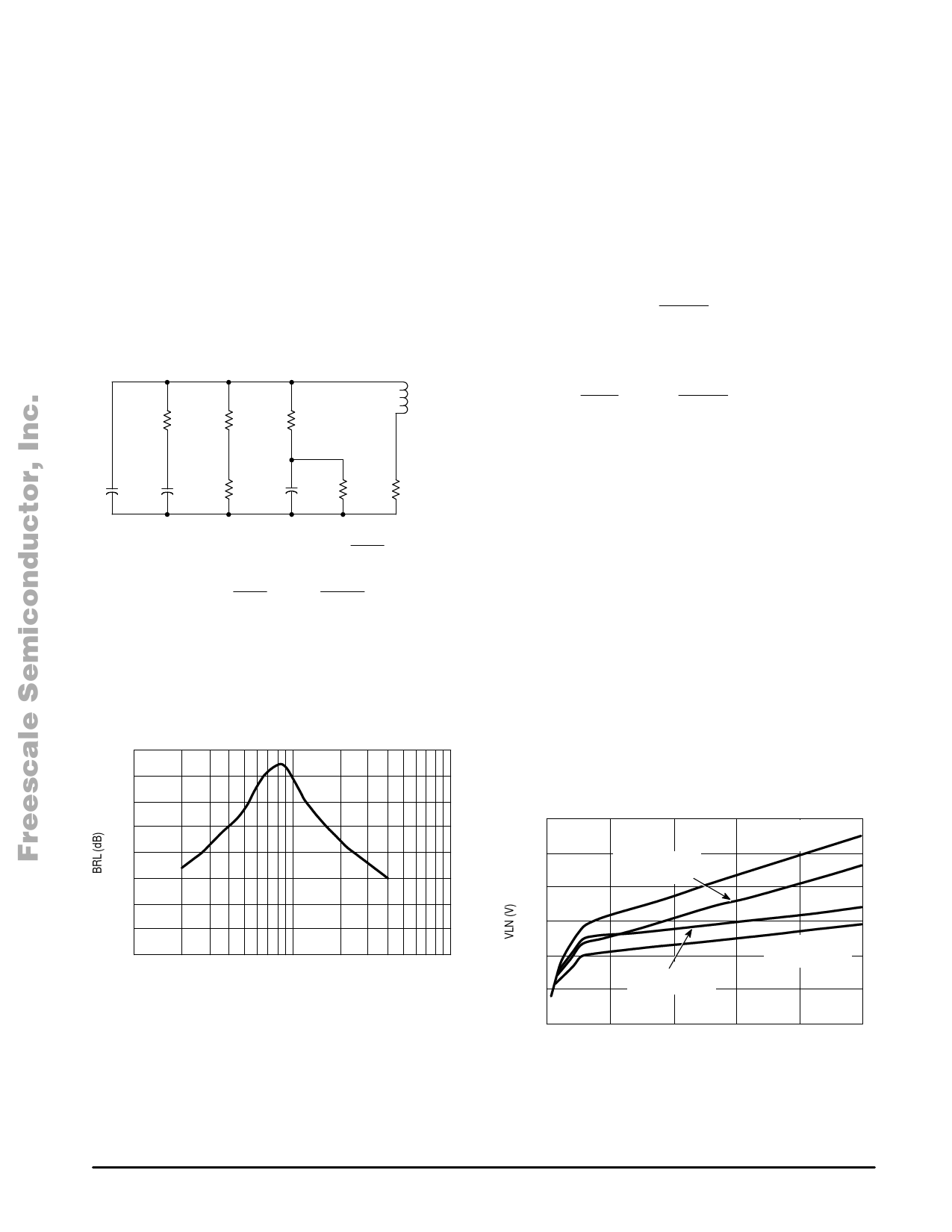
with the equivalent circuit shown in Figure 2.
Figure 2. Equivalent of the AC impedance
ZVDD
620
Zbal
RREG1
360 k
Inductor
CVLN
10 n
CVDD
100 µ
RSLB
2.2 k
CREG
220 n
RREG
∞
Slope
+ Inductor
RREG1
x
CREG
x
RSLP
11
+ ǒ ) Ǔ Slope
RSLP
11
x
1
RREG1
RREG2
With the component values of the typical application, the
inductor calculates as 1.6 H. Therefore, in the audio range of
300 Hz to 3400 Hz, the set impedance is mainly determined
by ZVDD. As a demonstration, the impedance matching or
Balance Return Loss BRL is shown in Figure 3.
Figure 3. Balance Return Loss
40
35
30
25
20
15
10
5.0
0
100
1000
10000
f, FREQUENCY (Hz)
The influence of the frequency dependent parasitic
components is seen for the lower frequencies (Inductor) and
the higher frequencies (CVLN) by a decreasing BRL value.
DC Set Impedance
The line current flowing towards the MC33215 application
is partly consumed by the circuitry connected to VDD while
the rest flows into Pin VLN. At Pin VLN, the current is split up
into a small part for biasing the internal line drive transistor
and into a large part for supplying the speakerphone. The
ratio between these two currents is fixed to 1:10. The dc set
impedance or dc setting of the telephone as created by the
line driver and its external components can be approximated
with the equivalent of a zener voltage plus a series resistor
according to:
ǒ Ǔ + ) VLN Vzener ILN x Rslope
With:
ǒ Ǔ ǒ Ǔ + ) ) Vzener
0.2 x 1
RREG1
RREG2
10 µA x RREG1
+ ILN Iline – IVDD
+ ǒ ) Ǔ Rslope
RSLP
11
x
1
RREG1
RREG2
If RREG2 is not mounted, the term between the brackets
becomes equal to 1.
With the values shown in the typical application and under
the assumption that IVDD = 1.0 mA, the above formulas can
be simplified to:
ǒǒ Ǔ Ǔ + ) VLN 3.8 V
Iline – 1.0 mA x 20
ǒ Ǔ ^ ) 3.8 V Iline x 20
In the typical application this leads to a line voltage of 4.2 V
at 20 mA of line current with a slope of 20 Ω. Adding a 1.5 V
voltage drop for the diode bridge and the interruptor, the dc
voltage at tip–ring will equal 5.7 V.
If the dc mask is to be adapted to a country specific
requirement, this can be done by adjusting the resistors
RREG1 and RREG2, as a result, the zener voltage and the
slope are varied. It is not advised to change the resistor RSLP
since this changes many parameters. The influence of RREG1
and RREG2 is shown in Figure 4.
Figure 4. Influence of RREG1 and RREG2
on the DC Mask
12
.
RREG1 = 470 k
10
RREG2 = 220 k
RREG1 = 365 k
8.0
RREG2 = 220 k
6.0
4.0
RREG1 = 365 k
RREG2 = Infinite
RREG1 = 470 k
2.0
RREG2 = Infinite
0
0
20
40
60
80
100
Iline (mA)
As can be seen in Figure 4, for low line currents below
10 mA, the given dc mask relations are no longer valid. This
is the result of an automatic decrease of the current drawn
8
For More Information On This ProdMuOcTtO, ROLA ANALOG IC DEVICE DATA
Go to: www.freescale.com
Share Link: 