MC74LCX16543ADT Ver la hoja de datos (PDF) - Motorola => Freescale
Número de pieza
componentes Descripción
Lista de partido
MC74LCX16543ADT Datasheet PDF : 8 Pages
| |||
MC74LCX16543A
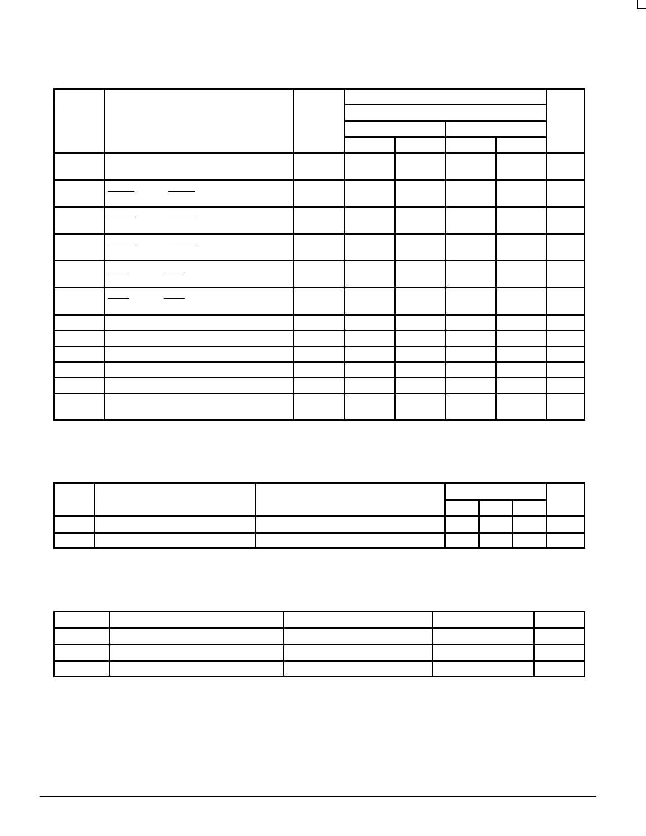
AC CHARACTERISTICS (tR = tF = 2.5ns; CL = 50pF; RL = 500Ω)
Limits
TA = –40°C to +85°C
Symbol
Parameter
VCC = 3.0V to 3.6V
VCC = 2.7V
Waveform
Min
Max
Min
Max
Unit
tPLH
tPHL
Propagation Delay
An to Bn or Bn to An
1
1.5
5.4
1.5
6.0
ns
1.5
5.4
1.5
6.0
tPLH
tPHL
Propagation Delay
LEBAn to An or LEABn to Bn
4
1.5
7.0
1.5
8.2
ns
1.5
7.0
1.5
8.2
tPZH
tPZL
Output Enable Time
OEBAn to An or OEABn to Bn
2
1.5
6.5
1.5
7.0
ns
1.5
6.5
1.5
7.0
tPHZ
tPLZ
Output Disable Time
OEBAn to An or OEABn to Bn
2
1.5
6.5
1.5
7.0
ns
1.5
6.5
1.5
7.0
tPZH
tPZL
Output Enable Time
EBAn to An or EABn to Bn
2
1.5
6.5
1.5
7.0
ns
1.5
6.5
1.5
7.0
tPHZ
tPLZ
Output Disable Time
EBAn to An or EABn to Bn
2
1.5
6.5
1.5
7.0
ns
1.5
6.5
1.5
7.0
ts
Setup Time, HIGH to LOW Data to LExxn
4
2.5
2.5
ns
th
Hold Time, HIGH to LOW Data to LExxn
4
1.5
1.5
ns
ts
Setup Time, HIGH to LOW Data to Exxn
4
2.5
2.5
ns
th
Hold Time, HIGH to LOW Data to Exxn
4
1.5
1.5
ns
tw
Latch Enable or Enable Pulse Width, LOW
4
3.0
3.0
ns
tOSHL
tOSLH
Output–to–Output Skew
(Note 3.)
1.0
ns
1.0
3. Skew is defined as the absolute value of the difference between the actual propagation delay for any two separate outputs of the same device.
The specification applies to any outputs switching in the same direction, either HIGH–to–LOW (tOSHL) or LOW–to–HIGH (tOSLH); parameter
guaranteed by design.
DYNAMIC SWITCHING CHARACTERISTICS
Symbol
Characteristic
Condition
TA = +25°C
Min Typ Max Unit
VOLP Dynamic LOW Peak Voltage (Note 4.)
VCC = 3.3V, CL = 50pF, VIH = 3.3V, VIL = 0V
0.8
V
VOLV Dynamic LOW Valley Voltage (Note 4.) VCC = 3.3V, CL = 50pF, VIH = 3.3V, VIL = 0V
0.8
V
4. Number of outputs defined as “n”. Measured with “n–1” outputs switching from HIGH–to–LOW or LOW–to–HIGH. The remaining output is
measured in the LOW state.
CAPACITIVE CHARACTERISTICS
Symbol
Parameter
CIN
CI/O
CPD
Input Capacitance
Input/Output Capacitance
Power Dissipation Capacitance
Condition
Typical
Unit
VCC = 3.3V, VI = 0V or VCC
7
pF
VCC = 3.3V, VI = 0V or VCC
8
pF
10MHz, VCC = 3.3V, VI = 0V or VCC
20
pF
LCX DATA
5
BR1339 — REV 3
MOTOROLA
Share Link: 