HCA600ACREF Ver la hoja de datos (PDF) - Intersil
Número de pieza
componentes Descripción
Lista de partido
HCA600ACREF Datasheet PDF : 11 Pages
| |||
HCA600ACREF
Absolute Maximum Ratings
Bus Voltage, VBUS . . . . . . . . . . . . . . . . . . . . . . . . . . . . . ±130V (Note 1)
+/-12V . . . . . . . . . . . . . . . . . . . . . . . . . . . . . . . . . . . . . . . . . . +/-15V
12VFLT. . . . . . . . . . . . . . . . . . . . . . . . . . . . . . . . . . . . . . . -Bus +15V
Audio Inputs . . . . . . . . . . . . . . 12V Differential Peak to Peak Voltage
NOTE:
1. WARNING: The voltages inside the shield, at the
edge connector, and on the speaker cables are
potentially deadly. Extreme caution is required.
Operating Conditions
Bus Voltage, VBUS . . . . . . . . . . . . . . . . . . . . . . . . . . . . . . . . . . . . . ±110V
+/-12V . . . . . . . . . . . . . . . . . . . . . . . . . . . . . . . . . . . . . . . . . . +/-12V
12VFLT . . . . . . . . . . . . . . . . . . . . . . . . . . . . . . . . . . . . . . -Bus +12V
Ambient Temperature Range . . . . . . . . . . . . . . . . . . . . . 0oC to 50oC
CAUTION: Stresses above those listed in “Absolute Maximum Ratings” may cause permanent damage to the device. This is a stress only rating and operation of the
device at these or any other conditions above those indicated in the operational sections of this specification is not implied.
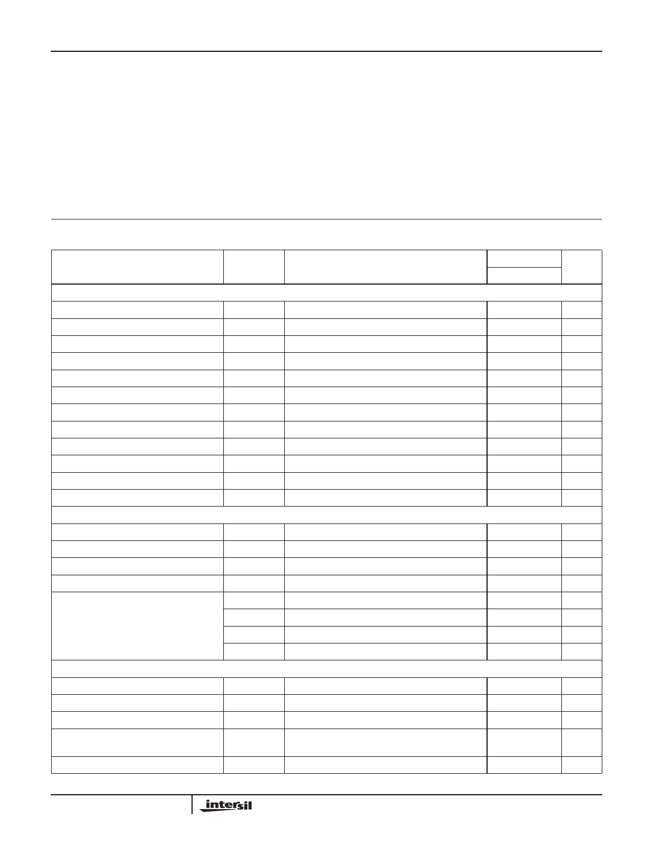
Electrical Specifications
PARAMETER
RLOAD = 8Ω, VBUS = ±110V, Supply Source Resistance < 2.5Ω, Storage Capacitor > 12,000µF, 12VFLT = 12V,
+/-12V = +/-12V
TA = 25oC
SYMBOL
TEST CONDITIONS
TYP
UNITS
SUPPLY SPECIFICATION
Minimum Bus Voltage
VBUS MIN 600W into 8Ω
±110
V
±VBUS RMS Current
IV BUS
1kHz Sine Wave, Full Output Power (8Ω load)
3
A
±VBUS RMS Current
IV BUS
1kHz Sine Wave, Full Output Power (4Ω load)
6
A
±VBUS,Q Average Current
IVBUSQ Quiescent Current, No Signal
60
mA
12V Float Current
I12VFLTBIAS Current supplied to power output gate driver circuitry
400
mA
Minimum +/-12V
VBIASmin 1kHz Sine Wave, Full Output Power (8Ω load)
11.5
V
±12V Max RMS Current
I+/-15V
No input signal
40
mA
Rising Under Voltage Lock Out Voltage
VUV Rising Bus voltage that activates the amplifier
±75
V
Falling Under Voltage Lock Out Voltage
VUV Falling Bus voltage that shuts down the amplifier
±50
V
ENABLE Threshold Voltage
VENABLE1 Amplifier starts at this voltage, input amplifier muted
1
V
ENABLE Threshold Voltage
VENABLE2 Input amplifiers active and entire amplifier active
2
V
ENABLE Internal Source Current
I ENABLE Internal “Pull Up” Current
25
µA
OUTPUT POWER AND EFFICIENCY
Maximum Output Power (Note 2)
Maximum Output Power (Note 2)
Maximum Output Power (Note 2)
Maximum Output Power (Note 2)
Efficiency
AMPLIFIER PERFORMANCE
PMAX8Ω
10% THD8Ω
PMAX4Ω
10% THD4Ω
PMAXEFF
PMAXEFF
PMAXEFF
PMAXEFF
THD = 1%, 1kHz, RLOAD = 8Ω
THD = 10%, 1kHz, RLOAD = 8Ω
THD = 1%, 1kHz, RLOAD = 4Ω
THD = 10%, 1kHz, RLOAD = 4Ω
POUT = 200W, 8Ω
POUT = 500W, 8Ω
POUT = 400W, 4Ω
POUT = 1000W, 4Ω
600
W
800
W
1000
W
1200
W
88
%
95
%
88
%
90
%
Total Harmonic Distortion + Noise
Signal to Noise Ratio
Output Noise
Intermodulation Distortion
PSRR (∆VOUT/∆VBUS)
THD+N
VSNR
VN
IMD
PSRR
POUT = 400W, RLOAD = 8Ω, 1kHz
Relative to full scale output, 600W into 8Ω
SMPTE, 60Hz and 7kHz, 4:1,
RLOAD = 8Ω at 25W Output
DC
0.015
110
200
0.02
300
%
dB
µV
%
µV/V
2
Share Link: 