PDM4M4030 Ver la hoja de datos (PDF) - Paradigm Technology
Número de pieza
componentes Descripción
Lista de partido
PDM4M4030 Datasheet PDF : 10 Pages
| |||
PDM4M4030
64K x 32 CMOS
1 Static RAM Module
Features:
n High-density 2 megabit Static RAM module
n Low profile 64-pin ZIP (Zig-zag In-line vertical
Package), 64-pin SIMM or Angled SIMM (Single
In-line Memory Module)
n Ultra fast access time: 10 ns (max.)
n Surface mounted plastic components on an epoxy
laminate (FR-4) substrate
n Single 5V (±10%) power supply
n Multiple VSS pins and decoupling capacitors for
maximum noise immunity
n Inputs/outputs directly TTL compatible
Description:
The PDM4M4030 is a 64K x 32 static RAM module
constructed on an epoxy laminate (FR-4) substrate
using eight 64K x 4 static RAMs in plastic SOJ
packages. Availability of four chip select lines (one
for each of two RAMs) provides byte access.
Extremely fast speeds can be achieved due to the use
of 256K Static RAMs fabricated in Paradigm’s high-
performance, high-reliability CMOS technology. The
PDM4M4030 is available with access times as fast as
10 ns with minimal power consumption.
The PDM4M4030 is packaged in a 64-pin FR-4 ZIP
2 (Zig-zag In-line vertical Package), a 64-pin SIMM or
Angled SIMM (Single In-line Memory Module). The
ZIP configuration allows 64 pins to be placed on a
package 3.65” long and 0.35” wide. At only 0.650”
high, this low-profile package is ideal for systems
3 with minimum board spacing. The SIMM configura-
tion allows use of edge mounted sockets to secure the
module.
4 All inputs and outputs of the PDM4M4030 are TTL
compatible and operate from a single 5V supply. Full
asynchronous circuitry requires no clock or refresh for
operation and provides equal access and cycle times
for ease of use.
5 Two identification pins (PD0 and PD1) are provided
for applications in which different density versions of
the module are used. In this way, the target system
6 can read the respective levels of PD0 and PD1 to
determine a 64K depth.
7
8
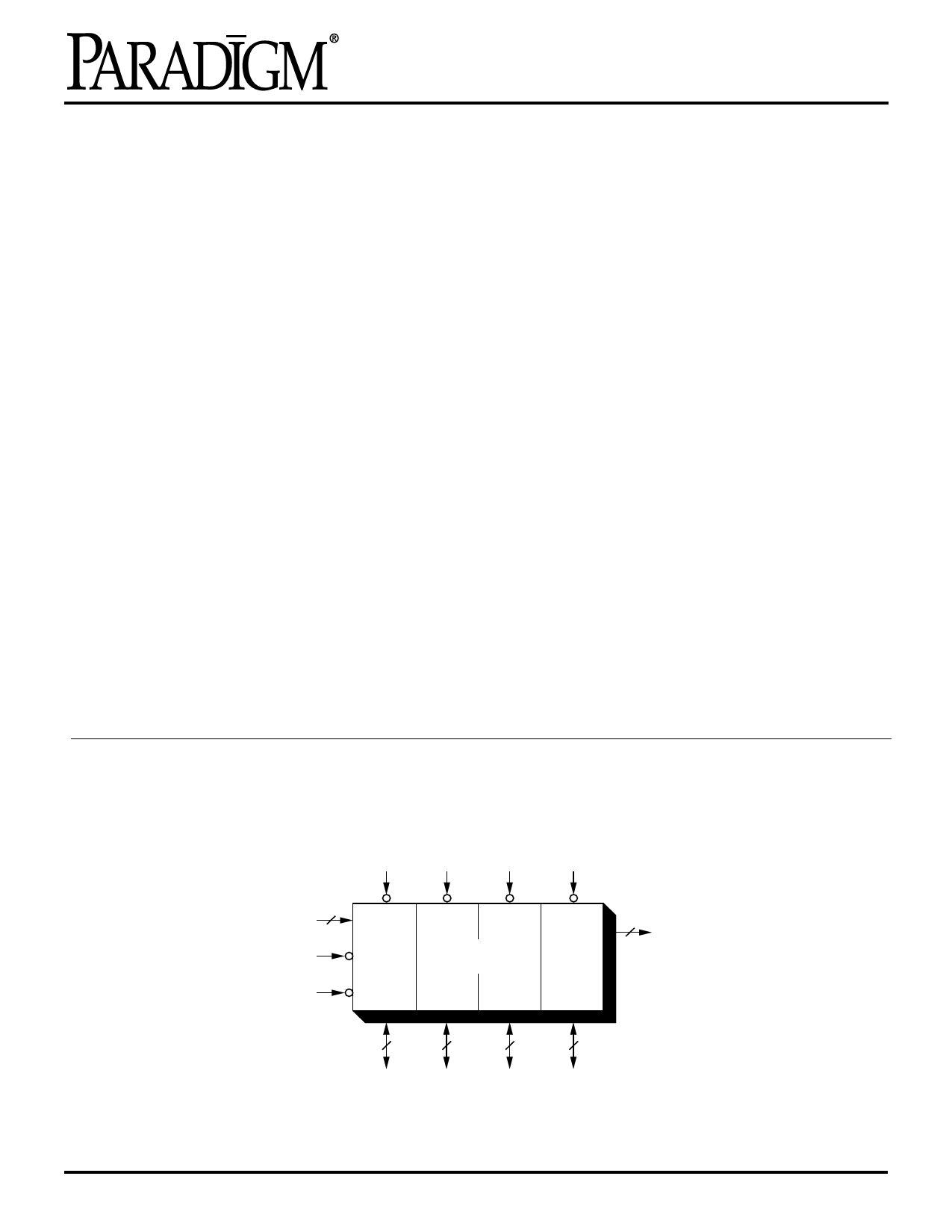
Functional Block Diagram
9
CS1 CS2 CS3 CS4
16
ADDRESS
WE
OE
8
64K x 32
RAM
8
8
8
I/O31-I/O0
2
PD
10
11
12
Rev 2.2 - 7/17/97
8-25
Share Link: 