NJM2527 Ver la hoja de datos (PDF) - Japan Radio Corporation
Número de pieza
componentes Descripción
Lista de partido
NJM2527 Datasheet PDF : 34 Pages
| |||
NJM2527
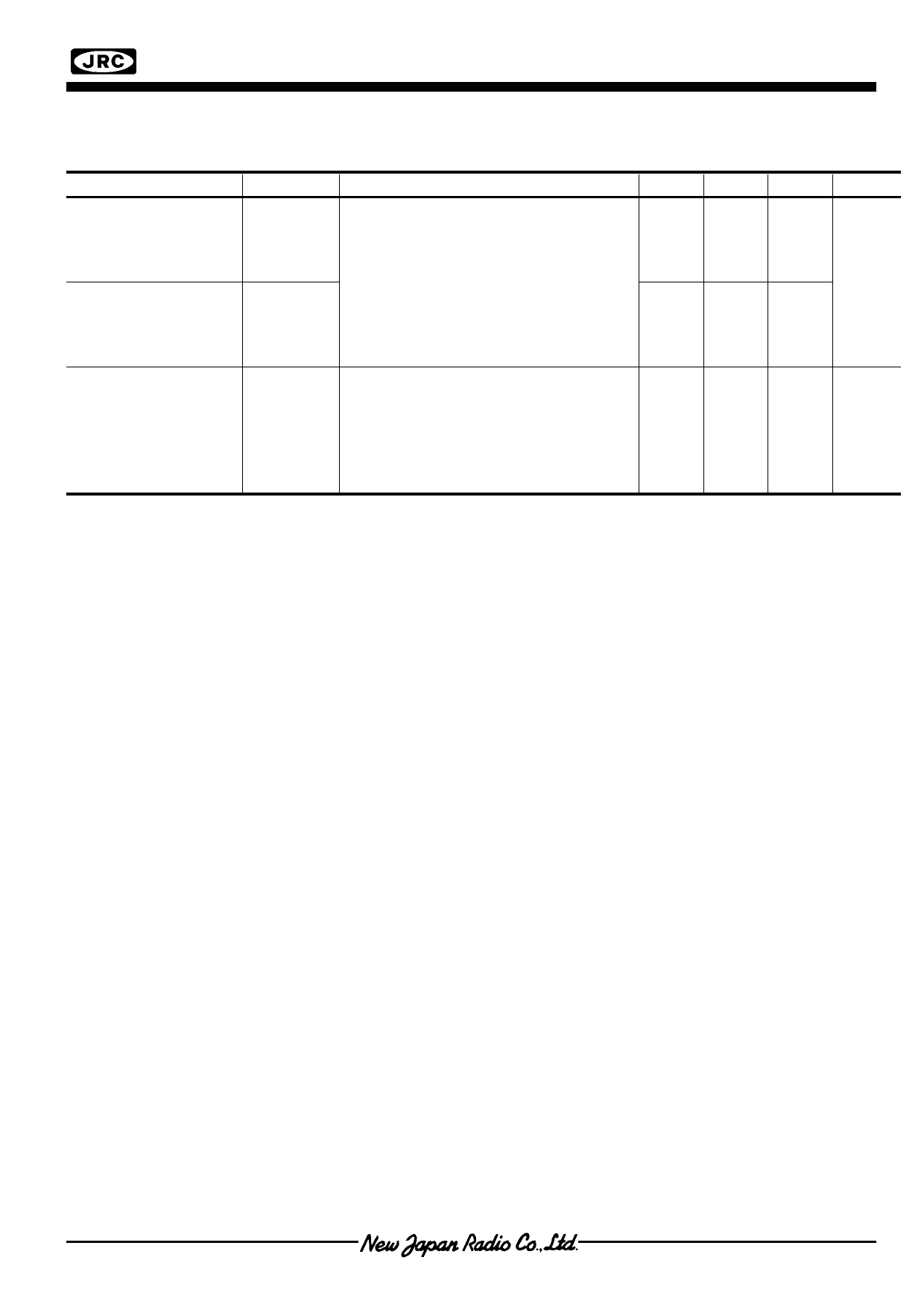
s ELECTRICAL CHARACTERISTICS
(Ta=25°C,VCC1=5V, VCC2=5V,TP20=TP31=TP45=2.5V,
TP19=2.8V,TP7=5V,TP38=1V,TP39=3V,TP44=0V,SW13=SW7=L)
PARAMETER
SYMBOL
TEST CONDITION (TP=IC Pin No.)
Demodulation
Relativity Phase
(R-Y/B-Y)
Demodulation
Relativity Phase
(G-Y/B-Y)
Demodulation Output
residual Carrier
ΘRB
ΘGB
VCR
SG6 (3.58MHz, 300mVpp) applied to
TP13, SG10 applied to TP5, SG2
applied to TP11, SG11 applied to
TP9. TP38=1.5V,TP39=3.0V,vary the
chroma phase on SG6, define the phase
at maximum output amplitude of TP48,
TP2, TP4 as ΘR,ΘG,ΘB.
ΘRB=ΘR-ΘB
ΘGB=ΘG-ΘB
SG6 (3.58MHz, 300mVpp) applied to
TP13, DC5V applied to TP5, SG2
Applied to TP11, SG11 applied to
TP4, adjust the chroma phase on SG6
for maximum the amplitude of TP4.
Measure the ratio of 7.159059MHz
component to the 15.734kHz component.
MIN.
-
-
-
TYP. MAX. UNIT
90
-
deg
240
-
-40
-
dB
Ver.3
- 11 -
Share Link: 