PBL38570 Ver la hoja de datos (PDF) - Ericsson
Número de pieza
componentes Descripción
Lista de partido
PBL38570 Datasheet PDF : 12 Pages
| |||
PBL 385 70
The circuit has further two temperature
and line current compensated DC supplies
DC1 and DC2. DC1 is a voltage supply for
supplying diallers, can also be used for
memory back up because it does not leak
any current back into the circuit. Typical
voltage 2.4V down to line voltage of 4.1V,
in case the line voltage is lower than 4.1V
calculate ; actual line voltage minus 1.9V.
In order to prevent noise entering the line,
a series resistor and a reservoir capaciotor
is recommended in series at this output.The
output current is given to be 2 mA in the
specification. In case this would not be
enough the current capability can be
increased by connecting the outputs of
DC1 and DC2 in parallel. The driving capa-
city will increase almost to the double but
the voltage drop across the necessary
series resistor will go upp thus limiting the
useful current.
The voltage level that is common for
both of these supplies is set by DC2. DC2
is a high precision, reference quality supply
that can be used to supply microphones,
opto couplers etc. The internally set voltage
can be adjusted with external resitors when
needed (RDC1 and RDC2).
The fourth DC-supply VPA has an
advantage that it does not influence the
circuits DC characteristics even at high
current drain. The supply has a floating
ground reference in the plus line in order to
minimize RFI problems and is used to
supply the power amplifier of a handsfree
telephone ( PBL3881, 38811---14 ). These
circuits have a current controlled charging
of the supply capacitor and the control
signal is taken across the resistor R6. In
case a monitor amplifier is required where
the ground reference is hardly necessary,
it can be supplied from VPA or like in alt. b
in fig. 17.
IL
+Line
Hook
switch
RLine
+
VPA
R3
V+C 4
1
PBL 38 570
V
Ref.
1.2V
+
VL
RFeed
+ Vexh.
b.
VMon.
a.
+
+
+
T
-
ƒ
Lim
2
3
+
C1 R6
-
8
9
15k
7
15k
14
-Line
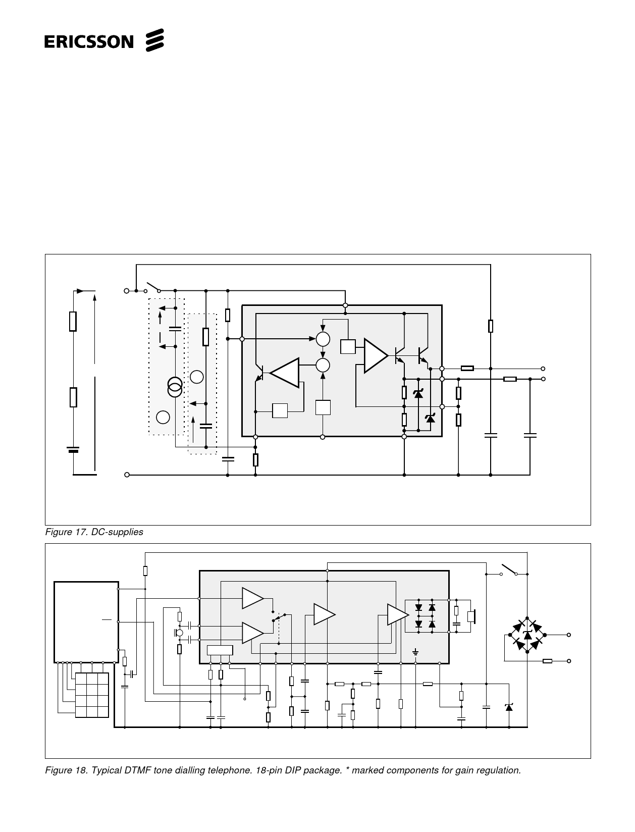
a. Supply arrangement for a handsfree system power amplifier. For ex. PBL 38811---14
b. Supply arrangement for a call monitor cicuit.
Figure 17. DC-supplies
1-10M
0-470Ω
RDC1
0-470Ω
VDC1
VDC2
RDC2
+ 4.7-47
µF
+ 4.7-47
µF
1-10M
VDD
10
AD
1
PBL 385 70
17
CMOS
DIALLER
MUTE 9
DTMF 12
GND
33k
123
45 6
789
*0 #
680p
3.3n
220Ω
MIC.
220Ω
1µF
12
13
1µF
DC-supply
89
7
AM
5
AT
6
11 3
2
AR
18
15
16 14
+4
100Ω
100Ω
47n
18k
100n
910Ω
6.2k
62k
+
47µF
Voltage
adjust
+
47µF
*
22k
*
560Ω
75Ω
11k
10Ω
11k
100n
Hook switch
100Ω
Rec.
10n
910Ω
15n
15V
+
47µF
Telephone line
10Ω
Figure 18. Typical DTMF tone dialling telephone. 18-pin DIP package. * marked components for gain regulation.
11
Share Link: 