PCA9515 Ver la hoja de datos (PDF) - Philips Electronics
Número de pieza
componentes Descripción
Lista de partido
PCA9515 Datasheet PDF : 11 Pages
| |||
Philips Semiconductors
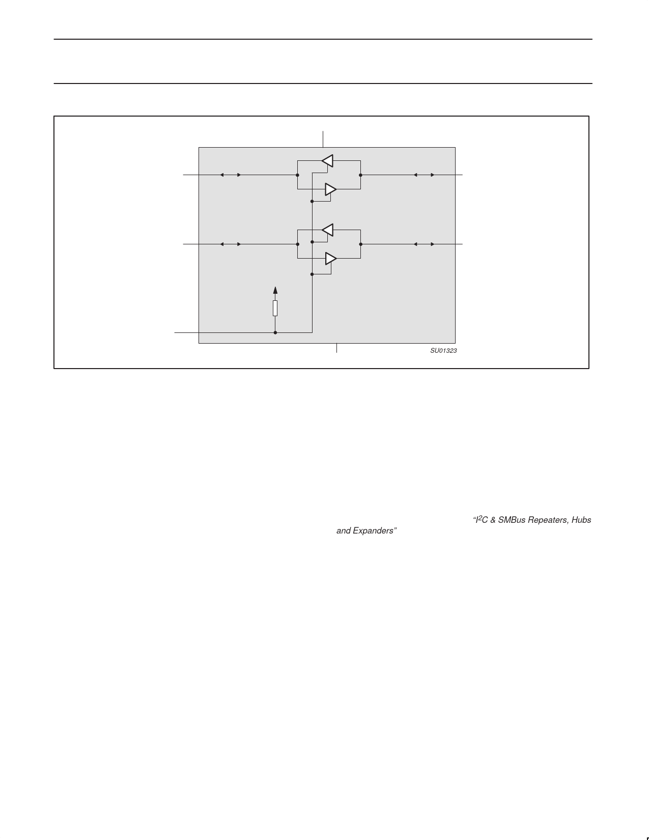
I2C-bus repeater
VCC
SDA0
PCA9515
Product data sheet
PCA9515
SDA1
SCL0
SCL1
PULL-UP
RESISTOR
EN
GND
SU01323
Figure 2. PCA9515 block diagram
The output pull-down of each internal buffer is set for approximately
0.5 V, while the input threshold of each internal buffer is set about
0.07 V lower, when the output is internally driven LOW. This
prevents a lock-up condition from occurring.
FUNCTIONAL DESCRIPTION
The PCA9515 BiCMOS integrated circuit contains two identical
buffer circuits which enable I2C and similar bus systems to be
extended without degradation of system performance.
The PCA9515 BiCMOS integrated circuit contains two bi-directional,
open drain buffers specifically designed to support the standard
low-level-contention arbitration of the I2C-bus. Except during
arbitration or clock stretching, the PCA9515 acts like a pair of
non-inverting, open drain buffers, one for SDA and one for SCL.
Enable
The EN pin is active high with an internal pull up and allows the user
to select when the repeater is active. This can be used to isolate a
badly behaved slave on power up until after the system power up
reset. It should never change state during an I2C operation because
disabling during a bus operation will hang the bus and enabling part
way through a bus cycle could confuse the I2C parts being enabled.
The enable pin should only change state when the global bus and
the repeater port are in an idle state to prevent system failures.
I2C Systems
As with the standard I2C system, pull-up resistors are required to
provide the logic HIGH levels on the Buffered bus. (Standard
open-collector configuration of the I2C-bus). The size of these
pull-up resistors depends on the system, but each side of the
repeater must have a pull-up resistor. This part designed to work
with standard mode and fast mode I2C devices in addition to SMBus
devices. Standard mode I2C devices only specify 3 mA output drive,
this limits the termination current to 3 mA in a generic I2C system
where standard mode devices and multiple masters are possible.
Under certain conditions higher termination currents can be used.
Please see Application Note AN255 “I2C & SMBus Repeaters, Hubs
and Expanders” for additional information on sizing resistors and
precautions when using more than one PCA9515/PCA9516 in a
system or using the PCA9515/16 in conjunction with the P82B96.
2004 Jun 24
3
Share Link: 