PCF8584 Ver la hoja de datos (PDF) - Philips Electronics
Número de pieza
componentes Descripción
Lista de partido
PCF8584 Datasheet PDF : 40 Pages
| |||
Philips Semiconductors
I2C-bus controller
Product specification
PCF8584
6.8.1 REGISTER S1 CONTROL SECTION
The write-only section of S1 enables access to registers S0, S0', S1, S2 and S3, and controls I2C-bus operation; see
Table 4.
6.8.1.1 PIN (Pending Interrupt Not)
When the PIN bit is written with a logic 1, all status bits are reset to logic 0. This may serve as a software reset function
(see Figs 5 to 9). PIN is the only bit in S1 which may be both read and written to. PIN is mostly used as a status bit for
synchronizing serial communication, see Section 6.8.2.
6.8.1.2 ESO (Enable Serial Output)
ESO enables or disables the serial I2C-bus I/O. When ESO is LOW, register access for initialization is possible. When
ESO is HIGH, I2C-bus communication is enabled; communication with serial shift register S0 is enabled and the S1 bus
status bits are made available for reading.
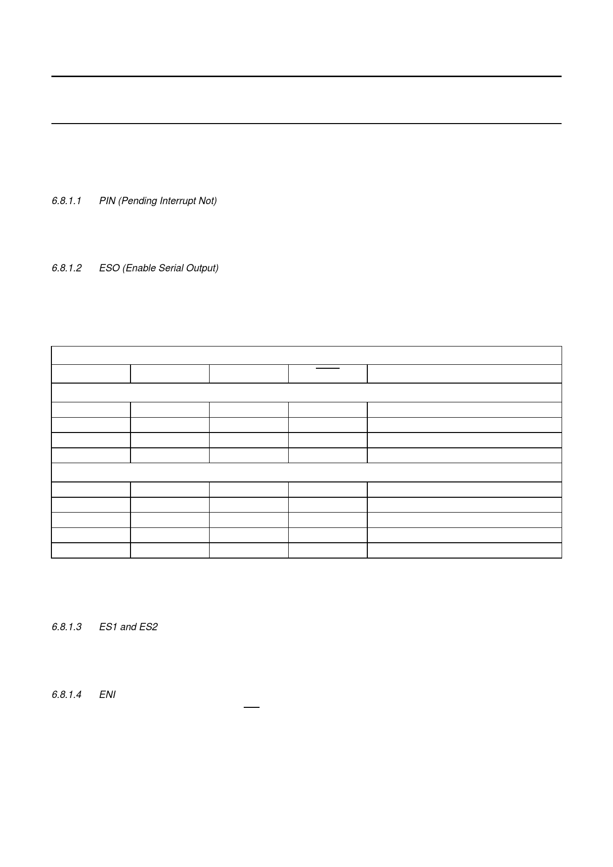
Table 5 Register access control; ESO = 0 (serial interface off) and ESO = 1 (serial interface on)
INTERNAL REGISTER ADDRESSING 2-WIRE MODE
A0
ES1
ES2
IACK
FUNCTION
ESO = 0; serial interface off (see note 1)
1
0
X
0
0
0
0
0
1
0
1
0
ESO = 1; serial interface on
1
0
X
1
0
X
0
0
0
0
0
1
X
0
X
1(2)
R/W S1: control
1(2)
R/W S0': (own address)
1(2)
R/W S3: (interrupt vector)
1(2)
R/W S2: (clock register)
1
W S1: control
1
R S1; status
1
R/W S0: (data)
1
R/W S3: (interrupt vector)
0
R S3: (interrupt vector ACK cycle))
Notes
1. With ESO = 0, bits ENI, STA, STO and ACK of S1 can be read for test purposes.
2. ‘X’ if ENI = 0.
6.8.1.3 ES1 and ES2
ES1 and ES2 control selection of other registers for initialization and control of normal operation. After these bits are
programmed for access to the desired register (shown in Table 5), the register is selected by a logic LOW level on
register select pin A0.
6.8.1.4 ENI
This bit enables the external interrupt output INT, which is generated when the PIN bit is active (logic 0).
This bit must be set to logic 0 before entering the long-distance mode, and remain at logic 0 during operation in
long-distance mode.
1997 Oct 21
10
Share Link: 