RH1084(RevC) Ver la hoja de datos (PDF) - Linear Technology
Número de pieza
componentes Descripción
Lista de partido
RH1084 Datasheet PDF : 4 Pages
| |||
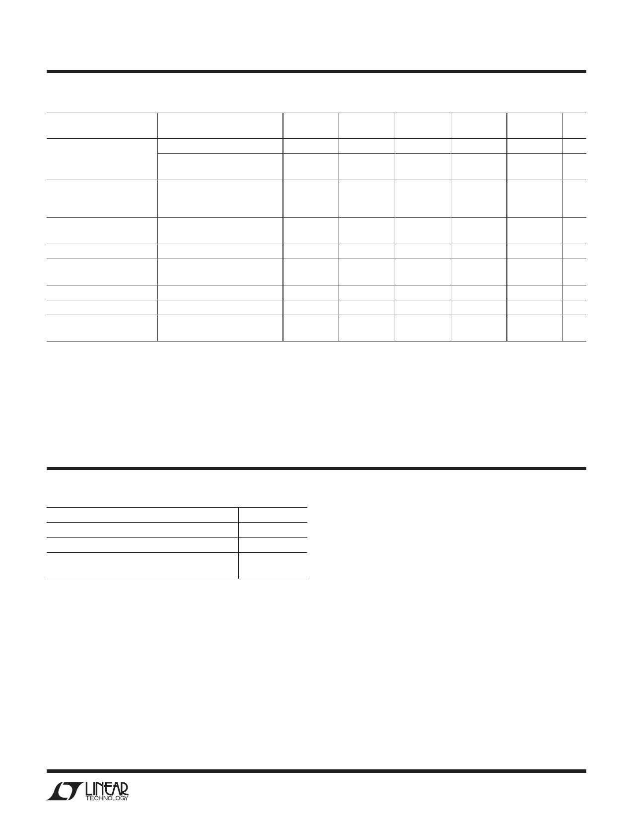
RH1084
TABLE 1A: ELECTRICAL CHARACTERISTICS (Postirradiation) TA = 25°C unless otherwise noted.
PARAMETER
CONDITIONS
Reference Voltage (Note 5)
IOUT = 10mA (VIN – VOUT) = 3V
10mA ≤ IOUT ≤ IFULL LOAD
1.5V ≤ (VIN – VOUT) ≤ 15V
Line Regulation (Notes 1, 2)
IOUT = 10mA
1.5V ≤ (VIN – VOUT) ≤ 15V
15V ≤ (VIN – VOUT) ≤ 25V
Load Regulation (Notes 1, 2, 5) (VIN – VOUT) = 3V
10mA ≤ IOUT ≤ IFULL LOAD
Dropout Voltage (Note 3)
ΔVREF = 1%, IOUT = FULLLOAD
Current Limit
(VIN – VOUT ) = 5V
(VIN – VOUT ) = 25V
Minimum Load Current
(VIN – VOUT ) = 25V
Adjust Pin Current
Adjust Pin Current Change
(Note 5)
10mA ≤ IOUT ≤ IFULL LOAD
1.5V ≤ (VIN – VOUT) ≤ 15V
10KRAD(Si)
20KRAD(Si)
50KRAD(Si) 100KRAD(Si) 200KRAD(Si)
MIN MAX MIN MAX MIN
MAX MIN MAX MIN MAX UNITS
1.234 1.258 1.23 1.257 1.225 1.253 1.22 1.247 1.205 1.241 V
1.210 1.275 1.219 1.275 1.215 1.275 1.210 1.275 1.203 1.275 V
0.2
0.5
0.3
1.5
5.5
5.5
0.3
0.3
10
120
5
0.21
0.5
0.3
1.55
5.4
0.3
10
120
5
0.23
0.25
0.5
0.5
0.3
0.35
1.65
5.25
0.3
10
120
5
1.8
5.0
0.3
10
120
5
0.3
%
0.5
%
0.4
%
2.0
V
A
A
10 mA
120 μA
5
μA
Note 1: See thermal regulation specifications for changes in output voltage
due to heating effects. Line and load regulation are measured at a constant
junction temperature by low duty cycle pulse testing.
Note 2: Line and load regulation are guaranteed up to the maximum power
dissipation of 45W for RH1084. Power dissipation is determined by the
input/output differential voltage and the output current. Guaranteed
maximum power dissipation will not be available over the full input/output
voltage range.
Note 3: Dropout voltage is specified over the full output current range of
the device. Test points and limits are shown on the Dropout Voltage curve
in the LT®1084 data sheet.
Note 4: Guaranteed by design, characterization, or correlation to other
tested parameters.
Note 5: IFULL LOAD is defined in the Current Limit curves in the standard
data sheet. For compliance with 883 revision C current density
specifications, the RH1084 is rated to 3A.
TABLE 2: ELECTRICAL TEST REQUIRE E TS
MIL-STD-883 TEST REQUIREMENTS
Final Electrical Test Requirements (Method 5004)
Group A Test Requirements (Method 5005)
Group C and D End Point Electrical Parameters
(Method 5005)
* PDA Applies to subgroup 1. See PDA Test Notes.
SUBGROUP
1*,2,3,4,5,6
1,2,3,4,5,6
1
PDA Test Notes
The PDA is specified as 5% based on failures from group A, subgroup 1,
tests after cooldown in accordance with method 5004 of MIL-STD-883
Class B. The verified failures of group A, subgroup 1, after burn-in divided
by the total number of devices submitted for burn-in in that lot shall be
used to determine the percent defective for the lot.
Linear Technology Corporation reserves the right to test to tighter limits
than those given.
Information furnished by Linear Technology Corporation is believed to be accurate and reliable.
However, no responsibility is assumed for its use. Linear Technology Corporation makes no represen-
tation that the interconnection of its circuits as described herein will not infringe on existing patent rights.
3
Share Link: 