RT8101 Ver la hoja de datos (PDF) - Richtek Technology
Número de pieza
componentes Descripción
Lista de partido
RT8101 Datasheet PDF : 15 Pages
| |||
Preliminary
RT8101/A
Figure 7 shows the DC-DC converter's gain vs. frequency.
The compensation gain uses external impedance networks
ZC and ZF to provide a stable, high bandwidth loop. High
crossover frequency is desirable for fast transient
response, but it often jeopardizes the system stability. In
order to cancel one of the LC filter poles, place the zero
before the LC filter resonant frequency. In the experience,
place the zero at 75% LC filter resonant frequency.
Crossover frequency should be higher than the ESR zero
but less than 1/5 of the switching frequency. The second
pole is placed at half of the switching frequency.
80 80
Loop Gain
60
40 40
20
Compensation
Gain
00
Modulator
-20 Gain
-40-40
-60-60
110H0zvdb(vo) vdb(comp2)11000vHd0zb(lo)
11.0kKHz
110K0Hzk
FrequFreequnenccyy (Hz)
11000K0Hzk
Figure 7. Bode Plot
1.01MHzM
Component Selection
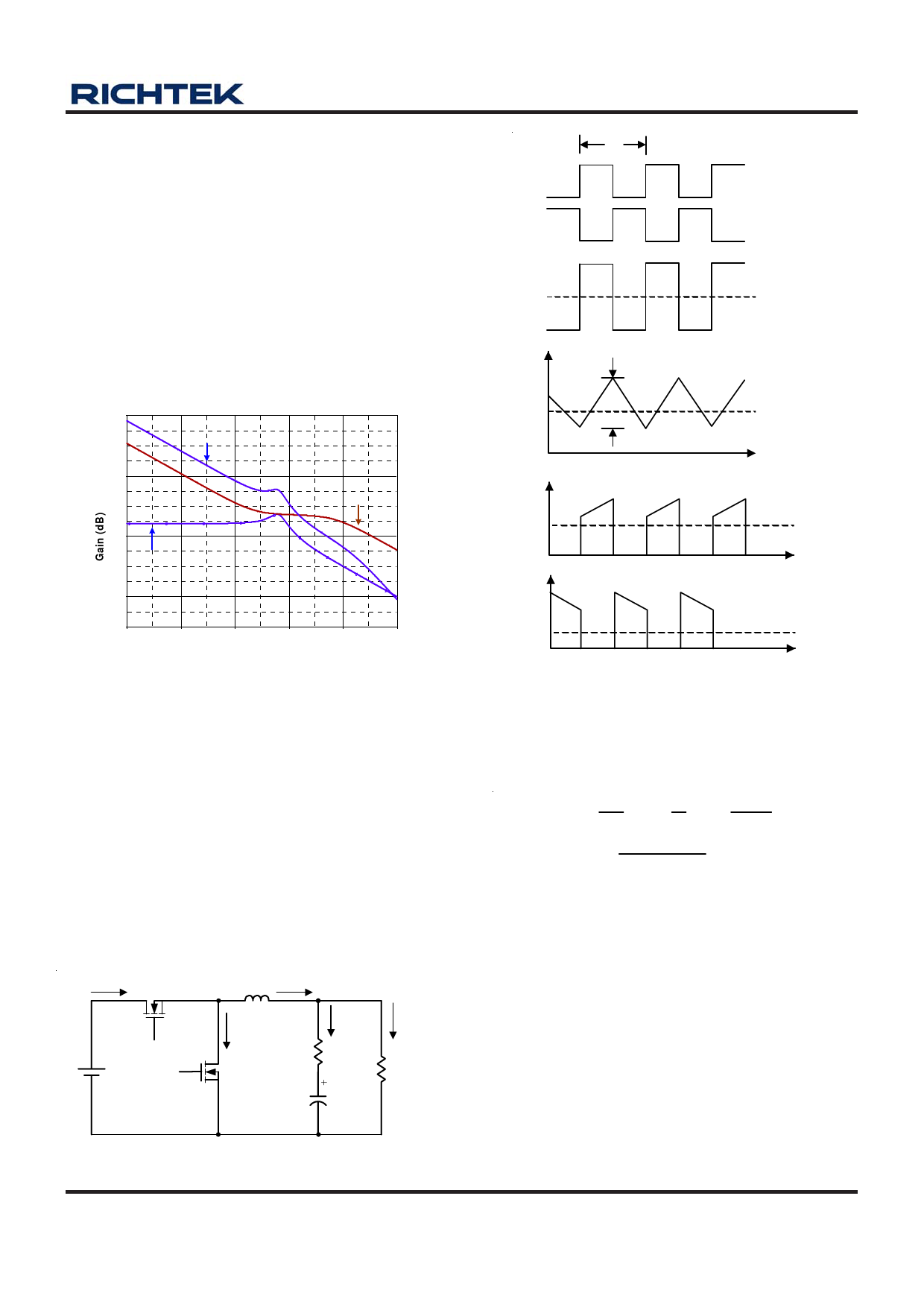
1) Inductor Selection
The selection of output inductor is based on the
considerations of efficiency, output power and operating
frequency. Low inductance value has smaller size, but
results in low efficiency, large ripple current and high output
ripple voltage. Generally, an inductor that limits the ripple
current (ΔIL) between 20% and 50% of the output current
is appropriate. Figure 8 shows the typical topology of
synchronous step-down converter and its related
waveforms.
iS1
S1
VIN
S2
L
IL
+ VL -
iS2
+
VOR
-
+
VOC
-
iC
rC
RL
COUT
IOUT
+
VOUT
-
TS
Vg1 TON TOFF
Vg2
VL
IL
ΔIL
IS1
VIN - VOUT
- VOUT
IL = IOUT
IS2
Figure 8. The waveforms of synchronous step-down
converter
According to Figure 8 the ripple current of inductor can be
calculated as follows :
VIN
−
VOUT
=
L
ΔIL
Δt
;
Δt
=
D
fs
;
D = VOUT
VIN
L
=
(VIN
−
VOUT
)
×
VOUT
VIN × fs ×
ΔIL
(1)
Where :
VIN = Maximum input voltage
VOUT = Output Voltage
Δt = S1 turn on time
ΔIL = Inductor current ripple
fS = Switching frequency
D = Duty Cycle
rC = Equivalent series resistor of output capacitor
DS8101/A-01 March 2007
www.richtek.com
11
Share Link: 