RF2670 Ver la hoja de datos (PDF) - RF Micro Devices
Número de pieza
componentes Descripción
Lista de partido
RF2670 Datasheet PDF : 12 Pages
| |||
RF2670
10
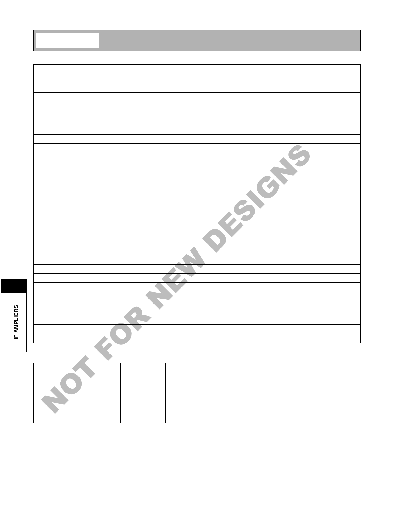
Pin Function Description
Interface Schematic
1
IN I-
Complementary input for the in-phase IF channel.
2
IN I+
Input for the in-phase IF channel.
3
GND2
Ground for VCC2.
4
DCFB I DC feedback capacitor for in-phase channel.
5
VCC2
Power supply for VGA amplifier 3, differential to single-ended converter,
and post filter.
6
GND3
Ground for VCC3.
7
IF OUT I Analog signal IF output for in-phase channel.
8
VCC3
Power supply for data amplifier.
9
I DATA
Logic-level data output for the in-phase channel. This is a digital output
signal obtained from the output of a Schmitt trigger.
10
RSSI I
Received signal strength indicator for the in-phase channel.
11
PD
Enable pin for the receiver circuits. PD >2.0V powers up all of the func-
tions. PD<1.0V turns off all of the functions.
12
GND1
Ground for VCC1 for both the in-phase and quadrature channels.
13
BW SEL1 Bandwidth select logic input. Pin 13 and pin 14 provide a two bit control
word for the setting of the IF bandwidth. See Table1. Additional filtering
should be used at the amplifiers to precisely control the 3dB bandwidth
of the system. See design information details about differential input fil-
ters.
14
BW SEL2 See pin 13.
15
Q DATA Logic-level data output for the quadrature channel. This is a digital out-
put signal obtained from the output of a Schmitt trigger.
16
RSSI Q Received signal strength indicator for the quadrature channel.
17
VREF
Gain control reference voltage.
18
IF OUT Q Analog signal IF output for quadrature channel.
19
VGC
Gain control voltage.
20
VCC1
Power supply for bias circuits and VGA amplifiers for both the in-phase
and quadrature channels.
21
DCFB Q DC feedback capacitor for quadrature channel.
22
GND1
Ground for VCC1 for both the in-phase and quadrature channels.
23
IN Q+
Plus input for quadrature channel
24
IN Q-
Minus input for quadrature channel
Table 1: Bandwidth Selection Controls
BWSEL1
0
0
1
1
BWSEL2
0
1
0
1
IF-3dB
Frequency
1 MHz
2 MHz
4 MHz
8 MHz
10-48
Rev A4 010820
Share Link: 