SM8135A Ver la hoja de datos (PDF) - Nippon Precision Circuits
Número de pieza
componentes Descripción
Lista de partido
SM8135A Datasheet PDF : 20 Pages
| |||
SM8135A
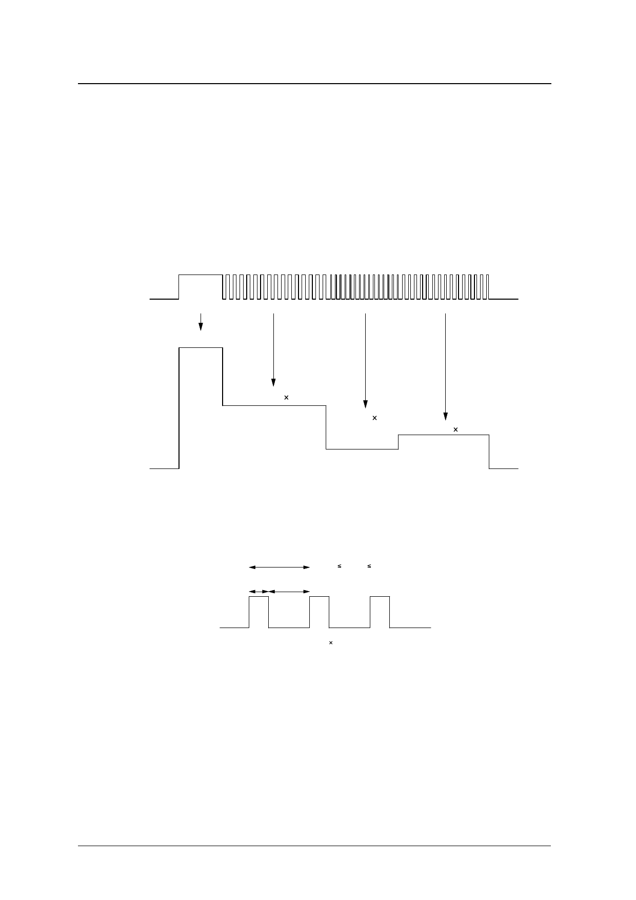
(2) Setting LED current using PWM signal input on EN
The EN input is used to enable/disable circuit operation, but it can also be switched at speed using a PWM sig-
nal input to set the average LED drive current value. When using PWM signal input on EN only for dimming
control, the average LED drive current is given by the multiplication of the maximum current value (ILED MAX)
set by RSET and the PWM signal ON duty percentage.
ILED = ILED MAX × ON Duty [%]
The PWM signal ON duty is defined in the following figures (“PWM duty”). The PWM signal operating fre-
quency range is 10kHz to 100kHz (10µs to 100µs per period), and the allowable duty range is 10 to 100%.
However, LED drive current that can be set by PWM signal has lower limit (= 2mA). When setting current to
2mA or less, even if the signal ON duty is within the allowable range, the current between pins varies widely.
High
EN
Low
ILED MAX
DUTY100%
turn on
(ILED MAX)
DUTY50%
DUTY10%
DUTY25%
ILED
turn off
(0)
0
ILED = ILED MAX 50%
ILED = ILED MAX 10%
ILED = ILED MAX 25%
turn off
(0)
Dimming control with PWM signal
1period
10µsec 1period 100µsec
ON
OFF
interval interval Duty [%] = ON interval/1period
ON
OFF
ILED = ILED MAX Duty [%]
PWM duty
SEIKO NPC CORPORATION —6
Share Link: 