LA2650 Ver la hoja de datos (PDF) - SANYO -> Panasonic
Número de pieza
componentes Descripción
Lista de partido
LA2650 Datasheet PDF : 13 Pages
| |||
LA2650
Notes on LA2650 Operation
LPF cutoff frequency
Use the following formula to calculate the cutoff frequency:
· fc = 1/(2πCR) Hz
However: R = 50 kΩ, since the resistor is on chip.
Thus the cutoff frequency can be set by the external capacitor.
Example: C = 0.039 µF (As in the sample application circuit)
fc = 81.6 Hz
Maximum boost gain
Use the following formula to calculate the maximum boost gain.
· BASS OUT total gain (GB) = α +4 × 20 log10 (1 + 4π2f2C2R2)–1/2 + β
Here,
α = Boost gain (20, 25, 30, or 35 dB)
β = Addition level (0, –3, –6, –9, –15, –20, –25, or –35 dB)
f: Frequency
C: The LPF external capacitor
R = 50 kΩ (built in)
Example: When α = 35 dB, β = 0 dB, f = 50 Hz, C = 0.039 µF (As in the application circuit)
GB = 29.46 dB
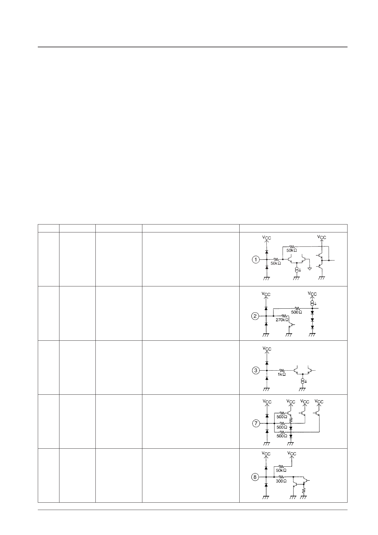
Pin Functions
Pin No.
1
20
Pin
IN-L
IN-R
Pin voltage (V)
1/2 VCC
Pin function
Signal input pin
The input impedance is 50 kΩ
Equivalent circuit
2 BOOST
0.7 to 2
ON/OFF
SMOOTHING
Smoothing pin for boost on/off switching
3 ENABLE
4 DATA
5 CLOCK
Apply either 0 or 5 V. Serial control data input pins
7 DET-OUT
1.7 to 3.5
The detection attack and recovery times are set
by the external resistor and capacitor connected
to this pin.
8 LED
VCC max.
LED cathode
Influx current: 20 mA (maximum)
Continued on next page.
No. 5652-6/13
Share Link: 