ELM380P Ver la hoja de datos (PDF) - Elm Electronics
Número de pieza
componentes Descripción
Lista de partido
ELM380P Datasheet PDF : 4 Pages
| |||
ELM380
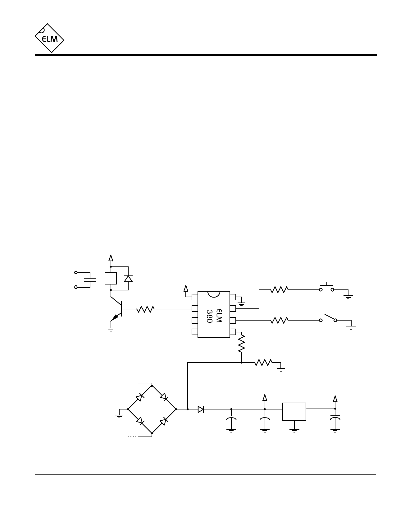
Example Application
Figure 1 shows the ELM380 used in a typical
battery charger control circuit.
Power for this circuit is obtained from a 12V supply,
as shown. Usually there will be a voltage of about this
level available if the charger is to support 9V batteries.
The 12V has been reduced to 5V through a 78L05 low
power regulator. This is a relatively inexpensive and
convenient way to obtain a stable voltage for a circuit
such as this.
The required 120Hz for the clock input is obtained
from the full-wave bridge as shown below. A series
diode has been added to prevent back-feed from the
filter capacitors (which would put a constant high level
on the clock input), and a 47KΩ resistor is connected in
series with pin 5 to limit the current through the
protection diodes when the AC bridge voltage exceeds
the ELM380 supply levels.
After the peak of each sine wave, the series diode,
and for a time, the bridge diodes, will not be conducting.
This means that the clock input will be left floating,
which is not advisable with CMOS circuits. To provide a
+12V
Charger
Enable
12V Relay
2N3904
1N4001
2.2KΩ
+5V
1
2
3
4
ground reference during these ‘open circuit’ periods, the
100KΩ resistor was connected from this point to VSS.
The rest of the circuit is straightforward. Two
switches are provided for control. Both the momentary
action ‘start’ switch and the toggle type ‘8/14’ switch
have 300Ω series resistors for added ESD protection,
and rely on the internal pullup resistors to provide a full
logic swing when operated. The 300Ω resistors aren’t
strictly required, but are a nice addition to consider for
added protection.
Only one of the outputs is used for this circuit. Its
active high level is used to drive the NPN transistor into
conduction and energize the relay coil. Depending on
the circuit, a direct connection to the load might be
used, but the use of a relay allows for general control of
many different loads.
There are many other uses that this circuit could be
put to. It could actually be used for almost any
application that needs long time intervals… Lawn
watering controls… Auto-off lighting systems…
300Ω
8
7
300Ω
6
5
47KΩ
100KΩ
start
8/14
open for 8 hrs
closed for 14
10VAC
60Hz
Supply
+12V
+5V
+
150µF
0.1µF
78L05
0.1µF
ELM380DSB
Figure 1. Typical Charger Control Circuit
Elm Electronics – Circuits for the Hobbyist
< http://www.elmelectronics.com/ >
4 of 4
Share Link: 