TA8405S Ver la hoja de datos (PDF) - Toshiba
Número de pieza
componentes Descripción
Lista de partido
TA8405S Datasheet PDF : 9 Pages
| |||
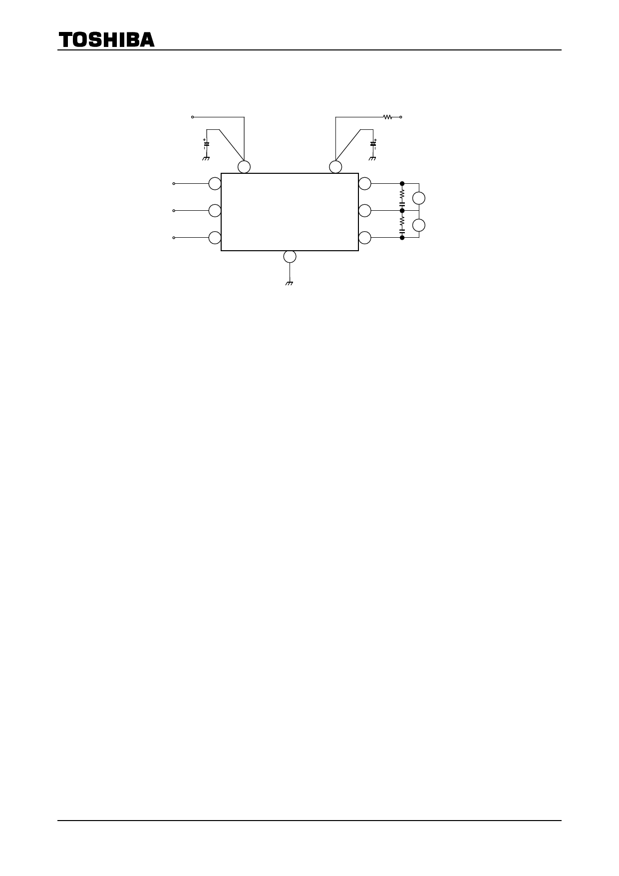
Application Circuit
VCC
R
VS
TA8405S
9
8
IN1
1
7
IN2
2
TA7T2A9814P0/5SS/F
IN3
3
MA
4
MB
6
5
GND
Note 1: Select an optimum value for the capacitor by experiment.
Note 2: A short-circuit between outputs, an output voltage fault, and a ground fault may break down the ICs and
supply an overvoltage and overcurrent to components around the them. Be very careful when designing the
output, VCC, VS, and ground lines.
Note in mind that mounting the IC in the reverse orientation may also cause a breakdown.
Note 3: Use a current limiting resistor (R) or fuse for overcurrent protection.
Note 4: When turning on the power for the ICs, apply VS after VCC (or VCC and VS simultaneously). When shutting
off the power, drop VS before VCC (or VS and VCC simultaneously).
When turning on the power (VCC), keep both the inputs (IN1, IN2 and IN3) on a low level.
7
2003-08-12
Share Link: 