TC74ACT157FT Ver la hoja de datos (PDF) - Toshiba
Número de pieza
componentes Descripción
Lista de partido
TC74ACT157FT Datasheet PDF : 10 Pages
| |||
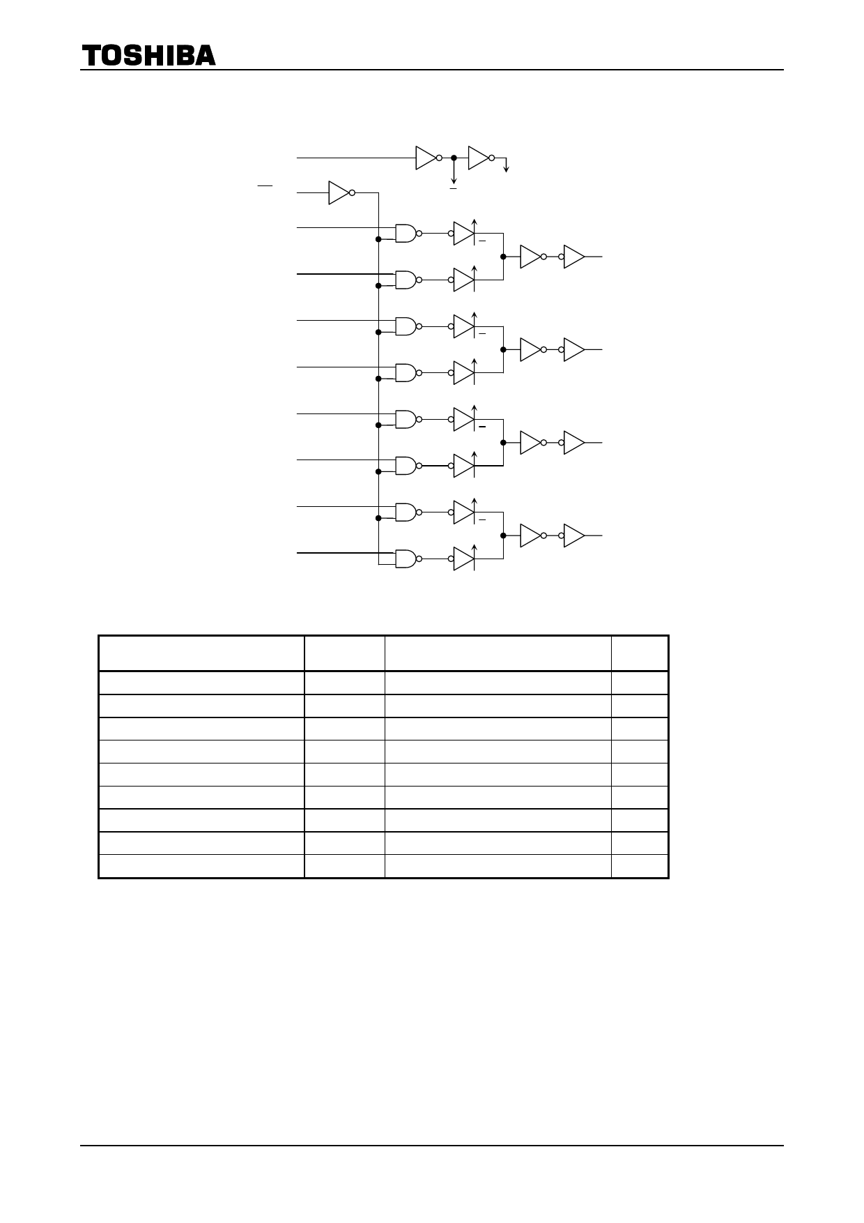
System Diagram
TC74ACT157P/F/FN/FT
1
SELECT
15
ST
2
1A
1B
3
5
2A
2B
6
11
3A
3B
10
14
4A
4B
13
φ
ϕ
ϕ
φ
ϕ
φ
ϕ
φ
ϕ
φ
4
1Y
7
2Y
9
3Y
12
4Y
Absolute Maximum Ratings (Note 1)
Characteristics
Symbol
Rating
Unit
Supply voltage range
DC input voltage
DC output voltage
Input diode current
Output diode current
DC output current
DC VCC/ground current
Power dissipation
Storage temperature
VCC
VIN
VOUT
IIK
IOK
IOUT
ICC
PD
Tstg
−0.5 to 7.0
V
−0.5 to VCC + 0.5
V
−0.5 to VCC + 0.5
V
±20
mA
±50
mA
±50
mA
±100
mA
500 (DIP) (Note 2)/180 (SOP/TSSOP)
mW
−65 to 150
°C
Note 1: Exceeding any of the absolute maximum ratings, even briefly, lead to deterioration in IC performance or
even destruction.
Using continuously under heavy loads (e.g. the application of high temperature/current/voltage and the
significant change in temperature, etc.) may cause this product to decrease in the reliability significantly
even if the operating conditions (i.e. operating temperature/current/voltage, etc.) are within the absolute
maximum ratings and the operating ranges.
Please design the appropriate reliability upon reviewing the Toshiba Semiconductor Reliability Handbook
(“Handling Precautions”/“Derating Concept and Methods”) and individual reliability data (i.e. reliability test
report and estimated failure rate, etc).
Note 2: 500 mW in the range of Ta = −40 to 65°C. From Ta = 65 to 85°C a derating factor of −10 mW/°C should be
applied up to 300 mW.
3
2007-10-01
Share Link: 