TSM1011(2016) Ver la hoja de datos (PDF) - STMicroelectronics
Número de pieza
componentes Descripción
Lista de partido
TSM1011
(Rev.:2016)
(Rev.:2016)
STMicroelectronics

TSM1011 Datasheet PDF : 14 Pages
| |||
TSM1011
6
Voltage and current control
Voltage and current control
6.1
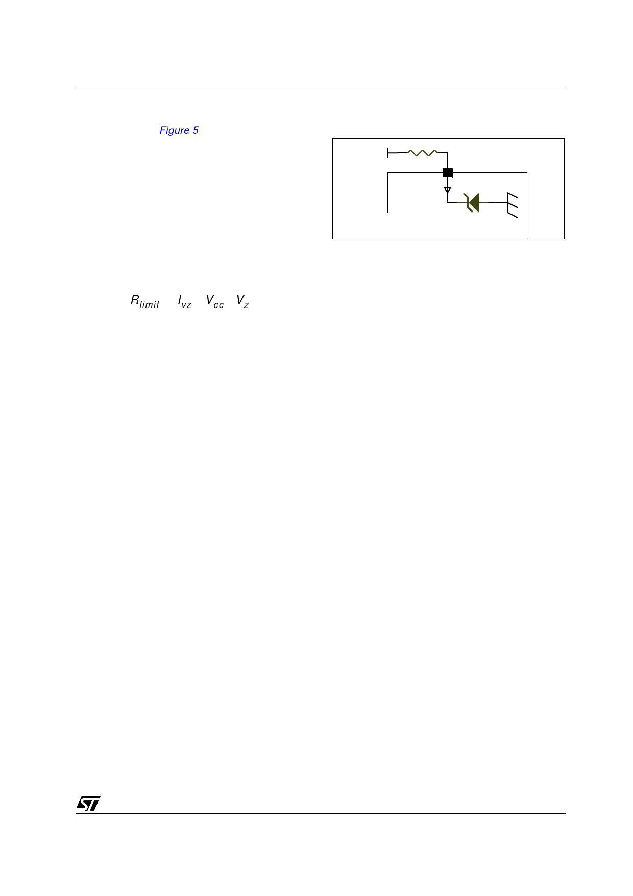
Note:
6.2
Voltage control
The voltage loop is controlled via a first transconductance operational amplifier, the resistor
bridge R1, R2, and the optocoupler which is directly connected to the output.
The relative values of R1 and R2 should be chosen in accordance with Equation 1:
Equation 1
R1 = R2 x VRef / (Vout - VRef)
where Vout is the desired output voltage.
To avoid the discharge of the load, the resistor bridge R1, R2 should have high impedance.
For this type of application, a total value of 100 K (or more) would be appropriate for the
resistors R1 and R2.
For example, with R2 = 100 K, Vout = 4.10 V, VRef = 2.5 V, then R1 = 41.9 K.
If the low drop diode is to be inserted between the load and the voltage regulation resistor
bridge to avoid current flowing from the load through the resistor bridge, this drop should be
taken into account in Equation 1 by replacing Vout by (Vout + Vdrop).
Current control
The current loop is controlled via the second transconductance operational amplifier, the
sense resistor Rsense, and the optocoupler.
Vsense threshold is achieved externally by a resistor bridge tied to the VRef voltage
reference. Its midpoint is tied to the positive input of the current control operational amplifier,
and its foot is to be connected to the lower potential point of the sense resistor, as shown in
Figure 4. The resistors of this bridge are matched to provide the best precision possible.
The control equation verifies that:
Equation 2
Rsense Ilim = Vsense
Vsense = --R-R----54-----+--V--R--r--e-5--f-
Equation 3
Ilim = ---R----4-----+--R--R--5---5----V-----r-R-e--f-s---e---n---s--e-
where Ilim is the desired limited current, and Vsense is the threshold voltage for the current
control loop.
Note that the Rsense resistor should be chosen taking into account the maximum dissipation
(Plim) through it during the full load operation.
DocID9310 Rev 2
7/14
14
Share Link: