US1050 Ver la hoja de datos (PDF) - Unisem
Número de pieza
componentes Descripción
Lista de partido
US1050 Datasheet PDF : 7 Pages
| |||
The ESR should be less than ;
( ) VIN − VOUT − ∆V − VDROP
ESR =
∆I
Where :
VDROP ≡ Input voltage drop
allowed in step 4
∆V ≡ Maximum regulator
dropout voltage
∆I ≡ Load current step
(5−3.5−1.2−0.15)
ESR =
=0.032 Ω
4.6
Selecting two Sanyo 1500 uF the same type as the
output capacitors meets our requirements.
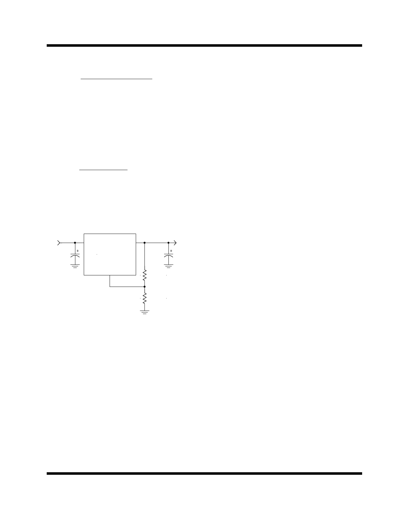
Figure 5 shows the completed schematic for our
example.
5V
C1
1500uF
Vin
Vout
US1050
Adj
3.50V
C2
5x 1500uF
R1
121
0.1%
R2
218
0.1%
1050app4-1.1
Figure 5 - Final Schematic for the
Intel VRE Application
Layout Consideration
The output capacitors must be located as close to
the Vout terminal of the device as possible. It is recom-
mended to use a section of a layer of the PC board as a
plane to connect the Vout pin to the output capacitors to
prevent any high frequency oscillation that may result
due to excessive trace inductance.
Rev. 1.3
10/27/00
US1050
2-39
Share Link: 