V7802-1000-SMT(2012) Ver la hoja de datos (PDF) - CUI INC
Número de pieza
componentes Descripción
Lista de partido
V7802-1000-SMT Datasheet PDF : 6 Pages
| |||
CUI Inc │ SERIES: V78-1000-SMT │ DESCRIPTION: NON-ISOLATED SWITCHING REGULATOR
date 10/31/2012 │ page 4 of 6
TYPICAL APPLICATION CIRCUIT
Vin
C1
GND
V7805-1000-SMT
1
5
10 7,9
6
R1
ON/OFF C4
R2
470pF
Vout
C2
GND
1. C1 and C2 are required for best performance and should
be fitted close to the converter pins.
2. See the capacitor values for C1 and C2 in the external
capacitor table below. These can be increased if required
and tantalum or low ESR electrolytic capacitors will also
suffice.
3. No parallel connection or plug and play.
EXTERNAL CAPACITOR TABLE
MODEL
C1 (Ceramic)
C2 (Ceramic)
V7802-1000-SMT
10 μF / 25 V
22 μF / 16 V
V7803-1000-SMT
10 μF / 25 V
22 μF / 16 V
V7805-1000-SMT
10 μF / 25 V
22 μF / 16 V
V7806-1000-SMT
10 μF / 25 V
22 μF / 16 V
APPLICATION EXAMPLE
L
DC/DC
+Vout
Vin
1 Converter 5
C1
GND
7,9
6
C2
C4
470pF
22 F
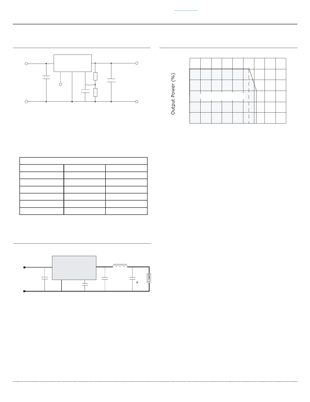
DERATING CURVE
120
100
80
60
40
20
0
-40
Safe Operating Area
0
40 71 85 120
Operating Temperature (°C)
REFLOW SOLDERING PROFILE
250
P ea k.Te mp 2 4 0 C
10 Sec Max
220 C
200
90 Sec Max
(>220 C)
150
100
50
0
Time (seconds)
To reduce output ripple, it is recommended to add a LC filter to the
output port.
L: Recommended parameter 10 ~ 47μH.
cui.com
Share Link: 