CS8402A-CS Ver la hoja de datos (PDF) - Cirrus Logic
Número de pieza
componentes Descripción
Lista de partido
CS8402A-CS Datasheet PDF : 34 Pages
| |||
CS8401A
digital audio specifications, V = 0 signifies the
audio signal is suitable for conversion to analog.
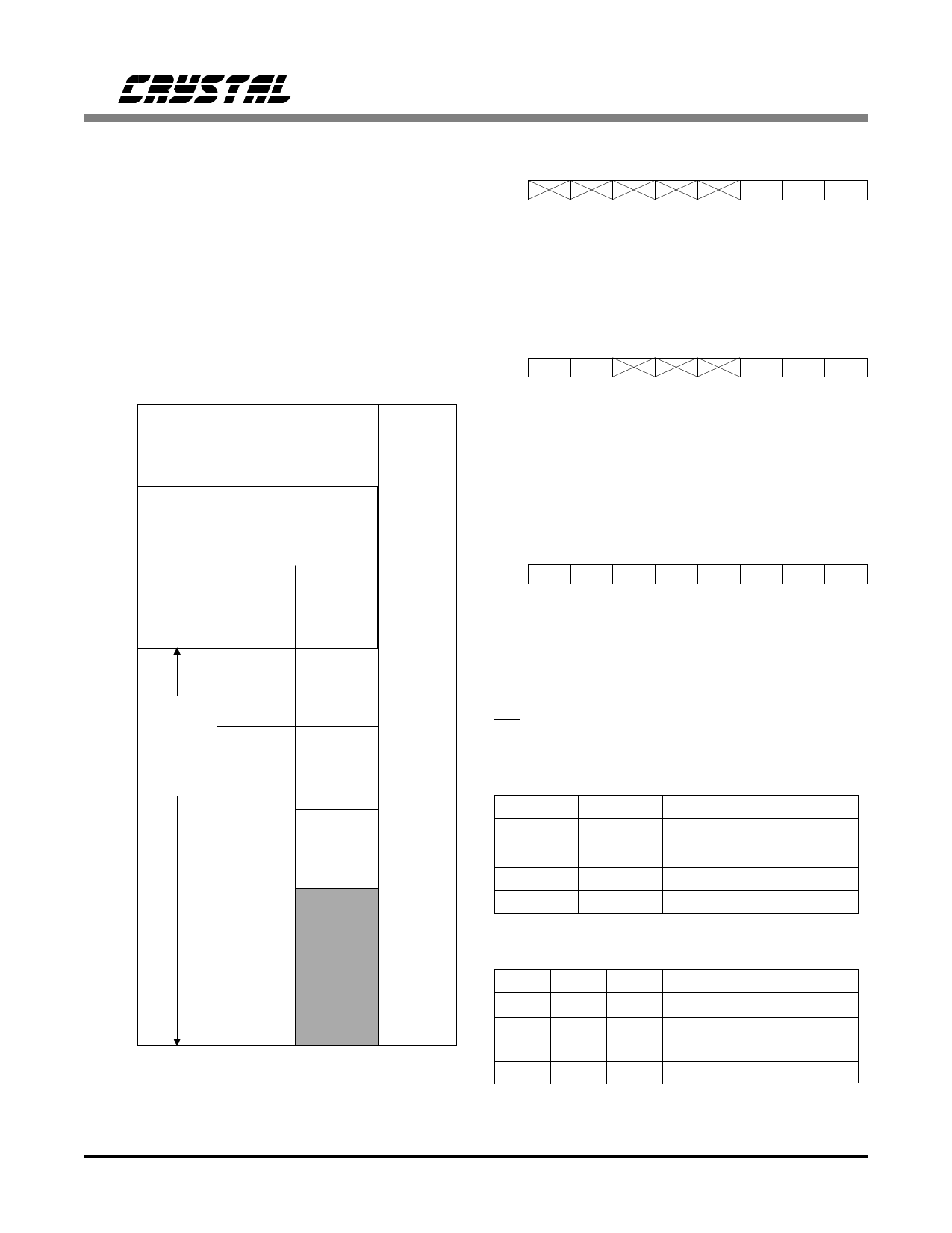
B1 and B0 select one of three modes for the
buffer memory. The different modes are shown
in Figure 5 and the bit combinations in Table 2.
More information on the different modes can be
found in the Buffer Memory section. Bit 2, CRCE, is
the channel status CRCC enable and should only be
used in professional mode. When CRCE is high, the
0
Status register 0
1
Control Register 1
2
Control Register 2
3
Control Register 3
4
5
User Data
6
7
8
9 1st Four
Bytes of
A C. S. Data
B
1st Four
Bytes of
C. S. Data
1st Four
Bytes of
Left C. S.
Data
U
N
D
E
F
C
I
AD
DE
D
R
E
F
10
Last
20 Bytes
Channel
C. S.
Data
Left
C. S.
Data
1st Four
N
E
D
S 11 Status
Bytes of
S 12
Data
Right
13
C. S. Data
14
15
Auxiliary
Right
16
Data
C. S.
Data
17
18
19
1A
1B
1C
1D
1E
1F
0
1
2
3
Memory Mode
Figure 5. CS8401A Buffer Memory Modes
7
6
5
4
3
2
1
0
X:00
FLAG2 FLAG1 FLAG0
FLAG2: High for first four bytes of channel status
FLAG1: Memory mode dependent - See figure 11
FLAG0: High for last two bytes of user data.
Figure 6. Status Register
7
6
5
4
3
2
1
0
X:01 BKST TRNPT
MASK2 MASK1 MASK0
BKST: Causes realignment of data block when set to "1".
TRNPT: Selects Transparent Mode appropriately setting data
delay through device
MASK2: Interrupt mask for FLAG2. A "1" enables the interrupt.
MASK1: Interrupt mask for FLAG1.
MASK0: Interrupt mask for FLAG0.
Figure 7. Control Register 1
7
6
5
4
3
2
1
0
X:02 M1
M0
V
B1
B0 CRCE MUTE RST
M1: with M0, selects MCK frequency.
M0: with M1, selects MCK frequency.
V: Validity bit of current sample.
B1: with B0, selects the buffer memory mode.
B0: with B1, selects the buffer memory mode.
CRCE: Channel status CRC Enable. Professional mode only.
MUTE: When clear, transmitted audio data is set to zero.
RST: When clear, drivers are disabled, frame counters cleared.
Figure 8. Control Register 2
M1
M0
MCLK
0
0
128× Input Word Rate
0
1
192× Input Word Rate
1
0
256× Input Word Rate
1
1
384× Input Word Rate
Table 1. MCLK Frequencies
B1
B0 Mode Buffer Memory Contents
0
0
0
Channel Status
0
1
1
Auxiliary Data
1
0
2 Independent Channel Status
1
1
3
Reserved
Table 2. Buffer Memory Modes
DS60F1
9
Share Link: 