VS-1N1199A Ver la hoja de datos (PDF) - Vishay Semiconductors
Número de pieza
componentes Descripción
Lista de partido
VS-1N1199A Datasheet PDF : 5 Pages
| |||
www.vishay.com
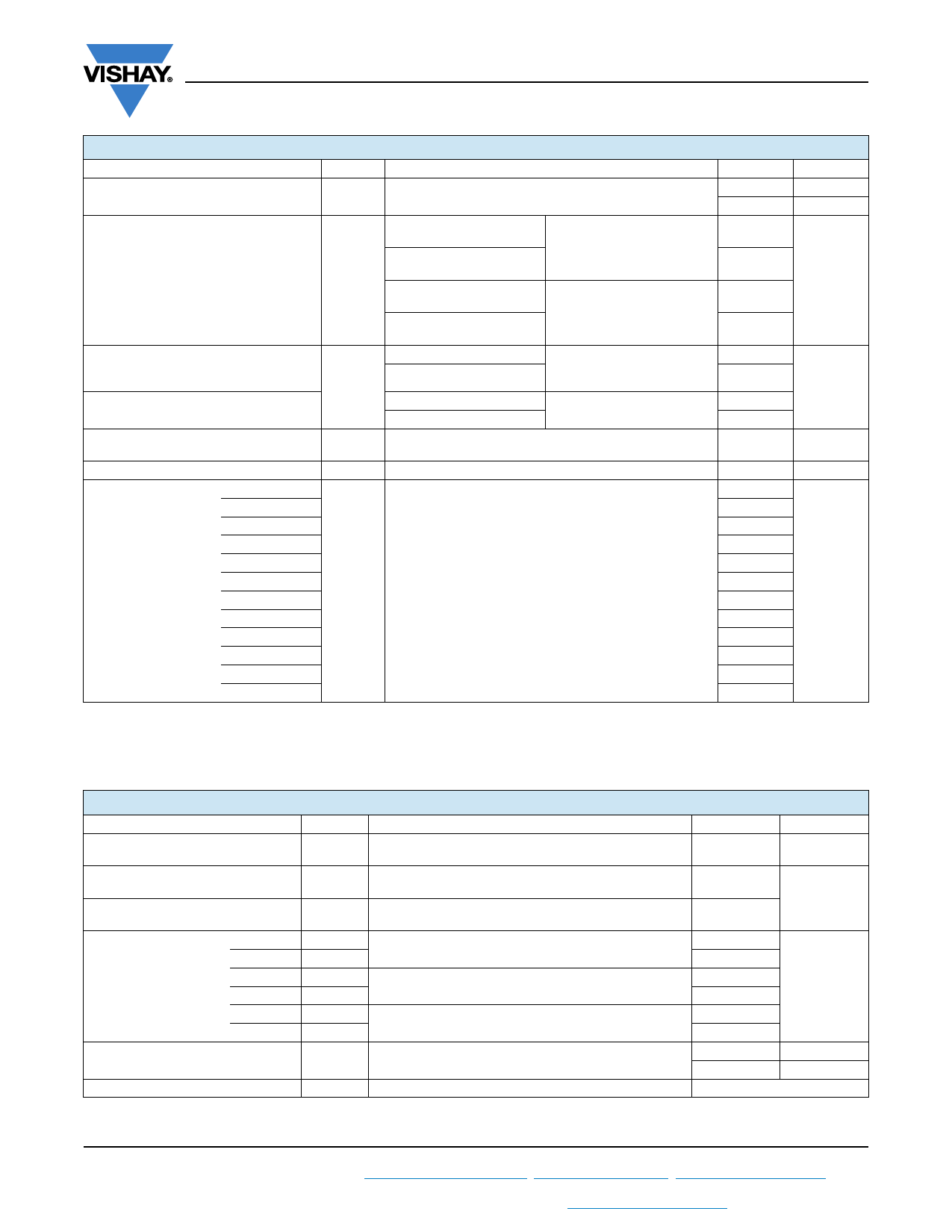
VS-1N1...A, VS-1N36..A Series
Vishay Semiconductors
FORWARD CONDUCTION
PARAMETER
SYMBOL
TEST CONDITIONS
Maximum average forward current
at case temperature
IF(AV)
180° sinusoidal conduction
Maximum peak one cycle non-repetitive
surge current
IFSM
Half cycle 50 Hz sine wave
or 6 ms rectangular pulse
Half cycle 60 Hz sine wave
or 5 ms rectangular pulse
Half cycle 50 Hz sine wave
or 6 ms rectangular pulse
Half cycle 60 Hz sine wave
or 5 ms rectangular pulse
Following any rated load
condition and with rated
VRRM applied
Following any rated load
condition and with VRRM
applied following surge = 0 V
Maximum I2t for fusing
Maximum I2t for individual
device fusing
Maximum I2t for individual
device fusing
I2t
I2t (1)
t = 10 ms
t = 8.3 ms
t = 10 ms
t = 8.3 ms
With rated VRRM applied
following surge,
initial TJ = 200 °C
With VRRM = 0 V following
surge, initial TJ = 200 °C
t = 0.1 ms to 10 ms, VRRM = 0 V following surge
Maximum forward voltage drop
Maximum average
reverse current
VRRM = 50 V
VRRM = 100 V
VRRM = 150 V
VRRM = 200 V
VRRM = 300 V
VRRM = 400 V
VRRM = 500 V
VRRM = 600 V
VRRM = 700 V
VRRM = 800 V
VRRM = 900 V
VRRM = 1000 V
VFM
IR(AV) (2)
IF(AV) = 12 A (38 A peak), TC = 25 °C
Maximum rated IF(AV) and TC
Notes
• JEDEC registered values are in bold
(1) I2t for time tx = I2t x tx
(2) Maximum peak reverse current (IRM) under same conditions 2 x rated IR(AV)
VALUES
12
150
230
240
275
285
260
240
370
340
3715
1.35
3.0
2.5
2.25
2.0
1.75
1.5
1.25
1.0
0.9
0.8
0.7
0.6
UNITS
A
°C
A
A2s
A2s
V
mA
THERMAL AND MECHANICAL SPECIFICATIONS
PARAMETER
SYMBOL
TEST CONDITIONS
Maximum operating case and
storage temperature range
TC, TStg
Maximum internal thermal
resistance, junction to case
RthJC
DC operation
Thermal resistance,
case to sink
RthCS Mounting surface, smooth, flat and greased
minimum
maximum
Torque applied to nut; non-lubricated threads
Mounting torque
minimum
maximum
Torque applied to nut; lubricated threads
minimum
maximum
Torque applied to device case; lubricated threads
Approximate weight
Case style
Note
• JEDEC registered values are in bold
JEDEC
VALUES
-65 to 200
UNITS
°C
2.0
°C/W
0.5
1.36 (12)
1.69 (15)
1.07 (9.45)
1.30 (11.55)
N·m
(lbf · in)
1.17 (10.35)
1.43 (12.65)
7.0
g
0.25
oz.
DO-203AA (DO-4)
Revision: 18-May-15
2
Document Number: 93493
For technical questions within your region: DiodesAmericas@vishay.com, DiodesAsia@vishay.com, DiodesEurope@vishay.com
THIS DOCUMENT IS SUBJECT TO CHANGE WITHOUT NOTICE. THE PRODUCTS DESCRIBED HEREIN AND THIS DOCUMENT
ARE SUBJECT TO SPECIFIC DISCLAIMERS, SET FORTH AT www.vishay.com/doc?91000
Share Link: 