DHRB34B471M2BB Ver la hoja de datos (PDF) - Unspecified
Número de pieza
componentes Descripción
Lista de partido
DHRB34B471M2BB Datasheet PDF : 20 Pages
| |||
!Note •PPleleaasseerreeaaddrraatitninggaanndd!!CCAAUUTTIOIONN((foforrsstotorraaggee,,ooppeerraatitningg,,rraatitningg,,ssooldldeerriningg,,mmoouunntitninggaannddhhaannddlilningg))ininththisisPcDatFalcoagtatolopgrteovepnretvsemnot ksimngokaindg/oarndb/uorrnbinugr,neintgc., etc.
C41E2.pdf 03.4.16
•TThhisisccaatatalologghhaassoonnlylytytyppiciacal sl pspeecicficfiactaiotinosn.sTbheecraeufosree,thyeorueaisrenroeqsupeascteedfotrodaeptapirloevdesopuercpifircoadtuiocntss.pTehceifirceafotioren,spoleratosetranpsparocvt ethoeuarppprroodvuacltsshpeeectifoicraptiroondsucotrstrpaencsifaiccatitohnesabpepfororevaolrsdheerientgf.or product specifications before ordering.
Typical Characteristics Data / Specifications and Test Methods
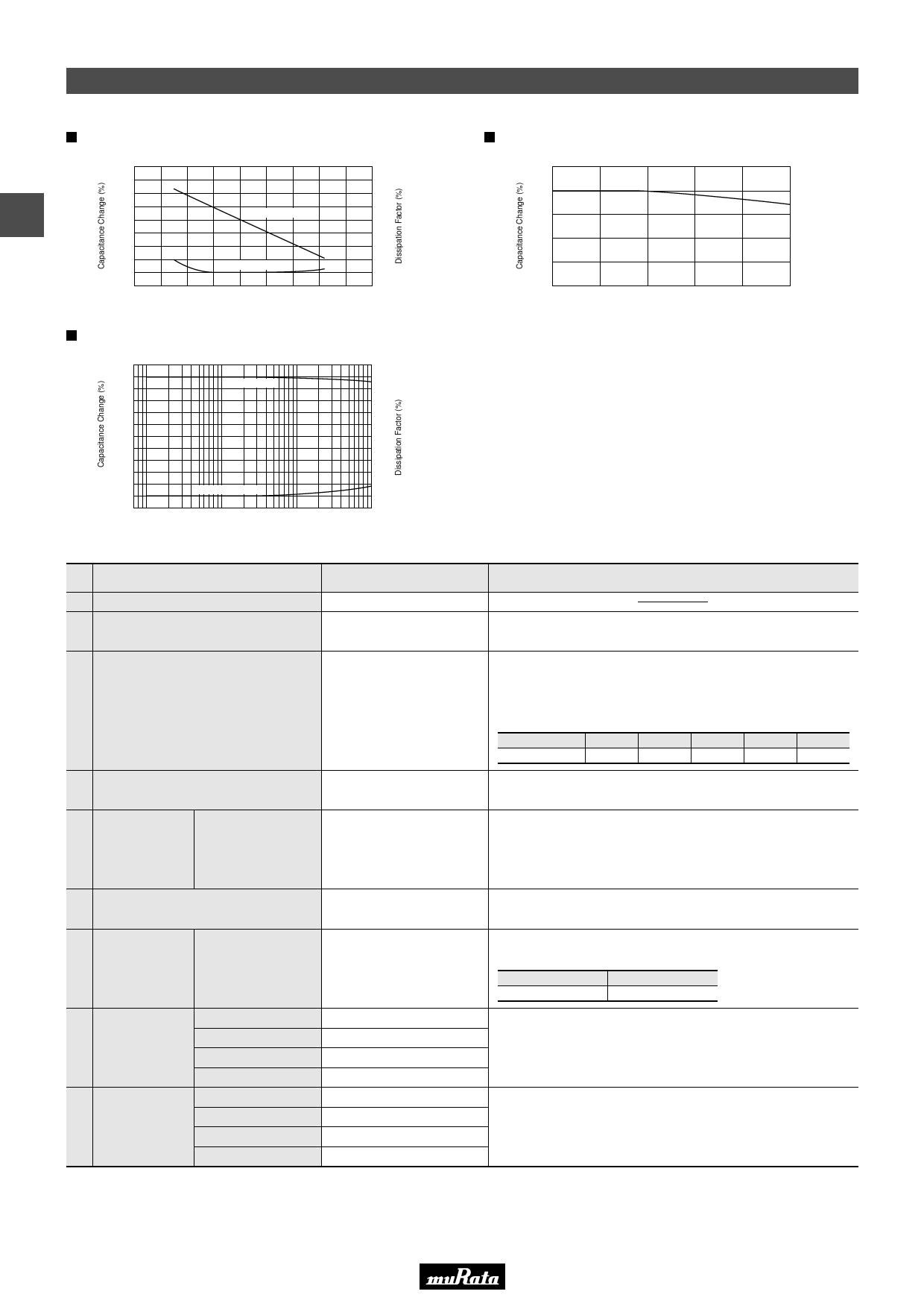
Temperature Characteristic
30
20
3
2
10
0
Capacitance
2
–10
–20
1
–30
Dissipation Factor
0
–40 –20
0 20 40 60
Temperature (°C)
80 100
Frequency Characteristic
0
–2
Capacitance
–4
–6
Dissipation Factor
1
10
100
Frequency (kHz)
6
4
2
0
1000
Typical Voltage Coefficient
0
Capacitance
–10
2
–20
0
20
40
60
80
100
DC Rated Voltage (%)
No
Item
1 Operating Temperature Range
2 Capacitance
3 Temperature Characteristics
Specifications
-20 to +85°C
Within the specified
tolerance.
Temperature coefficient
-4700±1000ppm/°C
(Temp. range: +20 to +85°C)
4 Dissipation Factor (D.F.)
0.3% max.
Dielectric
5
Strength
Between Terminal
No failure.
6 Insulation Resistance (I.R.)
10000MΩ min.
Strength of
7
Terminal
Torque Strength
Capacitor should not be
broken.
8 Life
Humidity
9 (Under Steady
State)
Appearance
Capacitance Change
D.F.
I.R.
Appearance
Capacitance Change
D.F.
I.R.
No marked defect.
Within ±5%
1.0% max.
1000MΩ min.
No marked defect.
Within ±5%
1.0% max.
1000MΩ min.
Testing Method
The capacitance should be measured at 20°C with 1±0.1kHz
and AC 1 to 5V(r.m.s.).
The capacitance measurement should be made at each step
specified in table.
Capacitance change from the value of step 3 should not exceed the
limit specified.
Step
1
Temp. (°C)
—
2
3
4
5
—
20±2 85±2 20±2
The dissipation factor should be measured at 20°C with 1±0.1kHz
and AC 1 to 5V(r.m.s.).
The capacitor should not be damaged when DC voltage of 150% of
the rated voltage is applied between the terminals for 60±5 sec. in
insulating liquid or gas.
(Charge/Discharge current V 50mA)
The insulation resistance should be measured with DC1000V within
60±5 sec. of charging.
When mounting the capacitor on equipment, be sure to mount
them within the torque strength values shown in the table below.
Terminal Type
ISO M4, No.8-32
torque (N·m)
1.5
Apply a DC voltage of 125% of the rated voltage for 100+24/-0 hrs. in
silicon oil at 85±2°C.
Post-treatment: Capacitor should be stored for 24 hrs. at *room
condition. (Charge/Discharge current V 50mA)
Set the capacitor for 100+24/-0 hrs. at 40±2°C in 90 to 95% relative
humidity. Post-treatment: Capacitor should be stored for 24 hrs. at
*room condition.
* "room condition" Temperature: 15 to 35°C, Relative humidity: 45 to 75%, Atmospheric pressure: 86 to 106kPa
12
Share Link: 