DHR4E4C101K2BB Ver la hoja de datos (PDF) - Unspecified
Número de pieza
componentes Descripción
Lista de partido
DHR4E4C101K2BB Datasheet PDF : 20 Pages
| |||
!Note •PPleleaasseerreeaaddrraatitninggaanndd!!CCAAUUTTIOIONN((foforrsstotorraaggee,,ooppeerraatitningg,,rraatitningg,,ssooldldeerriningg,,mmoouunntitninggaannddhhaannddlilningg))ininththisisPcDatFalcoagtatolopgrteovepnretvsemnot ksimngokaindg/oarndb/uorrnbinugr,neintgc., etc.
C41E2.pdf 03.4.16
•TThhisisccaatatalologghhaassoonnlylytytyppiciacal sl pspeecicficfiactaiotinosn.sTbheecraeufosree,thyeorueaisrenroeqsupeascteedfotrodaeptapirloevdesopuercpifircoadtuiocntss.pTehceifirceafotioren,spoleratosetranpsparocvt ethoeuarppprroodvuacltsshpeeectifoicraptiroondsucotrstrpaencsifaiccatitohnesabpepfororevaolrsdheerientgf.or product specifications before ordering.
Specifications and Test Methods 1
No.
Item
1 Operating Temperature Range
2 Capacitance
3 Dissipation Factor (D.F.)
4
Insulation
Resistance (I.R.)
Between
Lead Wires
Between
Lead Wires
5
Dielectric
Strength
Body Insulation
6 Temperature Characteristics
Specifications
-25 to +100˚C
Within the specified tolerance.
ZM
1.0% max.
B
2.5% max.
10000MΩ min.
No failure.
No failure.
Temp. Char.
ZM
B
Temp. Coefficient or
Max. Cap. Change
-4700±1000ppm/˚C
±10%
Testing Method
—
The capacitance should be measured at 20°C with 1±0.2kHz
and AC 5V(r.m.s.) max.
Same condition as capacitance.
The insulation resistance should be measured with DC1000V
within 60±5 sec. of charging.
The capacitor should not be damaged when DC voltage of
150% of the rated voltage is applied between the lead wires for
60±5 sec. in insulating liquid or gas.
(Charge/Discharge currentV50mA)
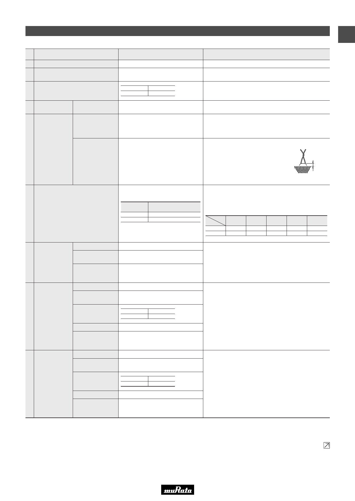
The capacitor is placed in the container with
metal balls of diameter 1mm so that each
lead wire, shortcircuited, is kept
approximately 2mm off the metal balls as
shown in the figure at right, and DC voltage
of 3kV is applied for 10 sec. between
capacitor lead wires and metal balls.
(Charge/Discharge currentV50mA)
Approx. 2mm
Metal balls
The capacitance measurement should be made at each step
specified in table.
Capacitance change from the value of step 3 should not
exceed the limit specified.
Step
Char.
ZM
B
1
—
20±2˚C
2
—
-25±3˚C
3
20±2˚C
20±2˚C
4
85±2˚C
85±2˚C
5
20±2˚C
20±2˚C
Appearance
Capacitance
7 Soldering Effect Change
Dielectric Strength
(Between
Lead Wires)
Appearance
Capacitance
Change
Humidity
8
(Under
Steady
D.F.
State)
I.R.
Dielectric Strength
(Between
Lead Wires)
Appearance
Capacitance
Change
No marked defect.
Within ±10%
No failure.
No marked defect.
Within ±10%
ZM
1.5% max.
B
4.0% max.
5000MΩ min.
No failure.
No marked defect.
Within ±10%
9 Life
D.F.
ZM
1.5% max.
B
4.0% max.
The lead wires should be immersed into the melted solder of
350±10˚C up to about 1.5 to 2.0mm from the main body for
3.5±0.5 sec.
Post-treatment: Capacitor should be stored for 24±2 hrs. at
*room condition.
Set the capacitor for 240±8 hrs. at 40±2˚C in 90 to 95% relative
humidity.
Post-treatment: Capacitor should be stored for 1 to 2 hrs. at
*room condition.
Apply a DC voltage of 125% of the rated voltage for 1000+-048
hrs. in silicon oil at 85±2˚C.
Post-treatment: Capacitor should be stored for 24±2 hrs. at
*room condition.
(Charge/Discharge currentV50mA)
I.R.
5000MΩ min.
Dielectric Strength
(Between
Lead Wires)
No failure
(Note) Tests for Dielectric Strength (between lead wires), Charge Discharge Test, Humidity, Temperature Cycle and Life should be performed with
specimens having molded resin (MR1023C : made by Murata) extending over 3mm on all the surface.
* "room condition" Temperature: 15 to 35D, Relative humidity: 45 to 75%, Atmospheric pressure: 86 to 106kPa
Continued on the following page.
5
Share Link: 