DHRB34C471M2BB Ver la hoja de datos (PDF) - Unspecified
Número de pieza
componentes Descripción
Lista de partido
DHRB34C471M2BB Datasheet PDF : 20 Pages
| |||
!Note •PPleleaasseerreeaaddrraatitninggaanndd!!CCAAUUTTIOIONN((foforrsstotorraaggee,,ooppeerraatitningg,,rraatitningg,,ssooldldeerriningg,,mmoouunntitninggaannddhhaannddlilningg))ininththisisPcDatFalcoagtatolopgrteovepnretvsemnot ksimngokaindg/oarndb/uorrnbinugr,neintgc., etc.
C41E2.pdf 03.4.16
•TThhisisccaatatalologghhaassoonnlylytytyppiciacal sl pspeecicficfiactaiotinosn.sTbheecraeufosree,thyeorueaisrenroeqsupeascteedfotrodaeptapirloevdesopuercpifircoadtuiocntss.pTehceifirceafotioren,spoleratosetranpsparocvt ethoeuarppprroodvuacltsshpeeectifoicraptiroondsucotrstrpaencsifaiccatitohnesabpepfororevaolrsdheerientgf.or product specifications before ordering.
1 Specifications and Test Methods
Continued from the preceding page.
No.
Item
Specifications
Testing Method
Appearance
Capacitance
Change
D.F.
I.R.
No marked defect.
Within ±10%
ZM
1.5% max.
B
4.0% max.
5000MΩ min.
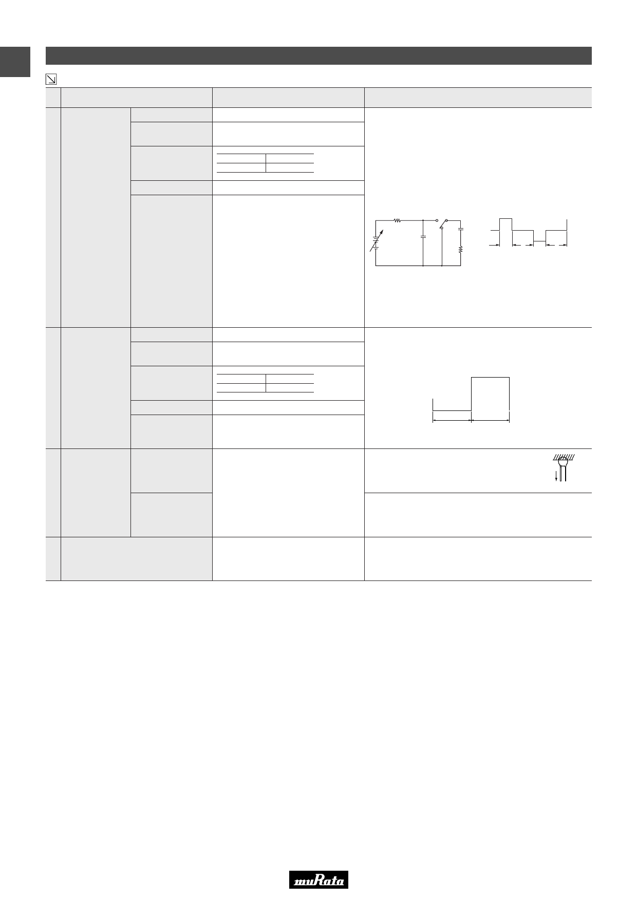
Charge discharge test should be measured in the following test
circuit and cycle.
Applied voltage : Rated voltage
Cycle time : 20000 cycle
Post-treatment : Capacitor should be stored for 4 hrs. at *room
condition.
Charge
10 Discharge
Test
Dielectric Strength
(Between
Lead Wires)
No failure.
Appearance
Capacitance
Change
No marked defect.
Within ±10%
<Circuit>
R1
SW
CX
C0
E
R2
<Cycle>
Charge Discharge
1
21
2
(sec.)
Cx : specimen
R1 : circuit protective resistor (300kΩ)
C0 : supplied energy for Cx. C0.=.10Cx
R2 : current limitting resistor (E/10Ω)
E : direct-current voltage source
Temperature cycle should be measured in the following test.
Cycle time : 5 cycle
Post-treatment : Capacitor should be stored for 4 hrs. at *room
condition.
11
Temperature
Cycle
D.F.
I.R.
Dielectric Strength
(Between
Lead Wires)
ZM
1.5% max.
B
4.0% max.
5000MΩ min.
No failure.
-30˚C
30
+100˚C
30
(min)
12
Strength
of Lead
Pull
Bending
Lead wire should not be cut off.
Capacitor should not be broken.
As shown in the figure at right, fix the body of the
capacitor and apply a tensile weight gradually to
each lead wire in the radial direction of the
W
capacitor up to 10N and keep it for 10±1 sec.
Each lead wire should be subjected to 5N of weight and bent
90˚ at the point of egress, in one direciton, then returned to its
original position and bent 90˚ in the opposite direction at the
rate of one bend in 2 to 3 sec.
13 Solderability of Leads
Lead wire should be soldered with
uniform coating on the axial direction
over 34– of the circumferential direction.
The lead wire of a capacitor should be dipped into a 25%
methanol solution of rosin and then into molten solder of
235±5˚C for 2±0.5 sec. In both cases the depth of dipping is up
to about 1.5 to 2.0mm from the root of lead wires.
(Note) Tests for Dielectric Strength (between lead wires), Charge Discharge Test, Humidity, Temperature Cycle and Life should be performed with
specimens having molded resin (MR1023C : made by Murata) extending over 3mm on all the surface.
* "room condition" Temperature: 15 to 35D, Relative humidity: 45 to 75%, Atmospheric pressure: 86 to 106kPa
6
Share Link: 