ST16C452CJ68 Ver la hoja de datos (PDF) - Exar Corporation
Número de pieza
componentes Descripción
Lista de partido
ST16C452CJ68 Datasheet PDF : 30 Pages
| |||
ST16C452/452PS
The generator divides the input 16X clock by any divisor
from 1 to 216 -1. The 452/452PS divides the basic
external clock by 16. The basic 16X clock provides table
rates to support standard and custom applications
using the same system design. The rate table is
configured via the DLL and DLM internal register func-
tions. Customized Baud Rates can be achieved by
selecting the proper divisor values for the MSB and LSB
sections of baud rate generator.
Programming the Baud Rate Generator Registers
DLM (MSB) and DLL (LSB) provides a user capability
for selecting the desired final baud rate. The example
in Table 5 below, shows the selectable baud rate table
available when using a 1.8432 MHz external clock
input.
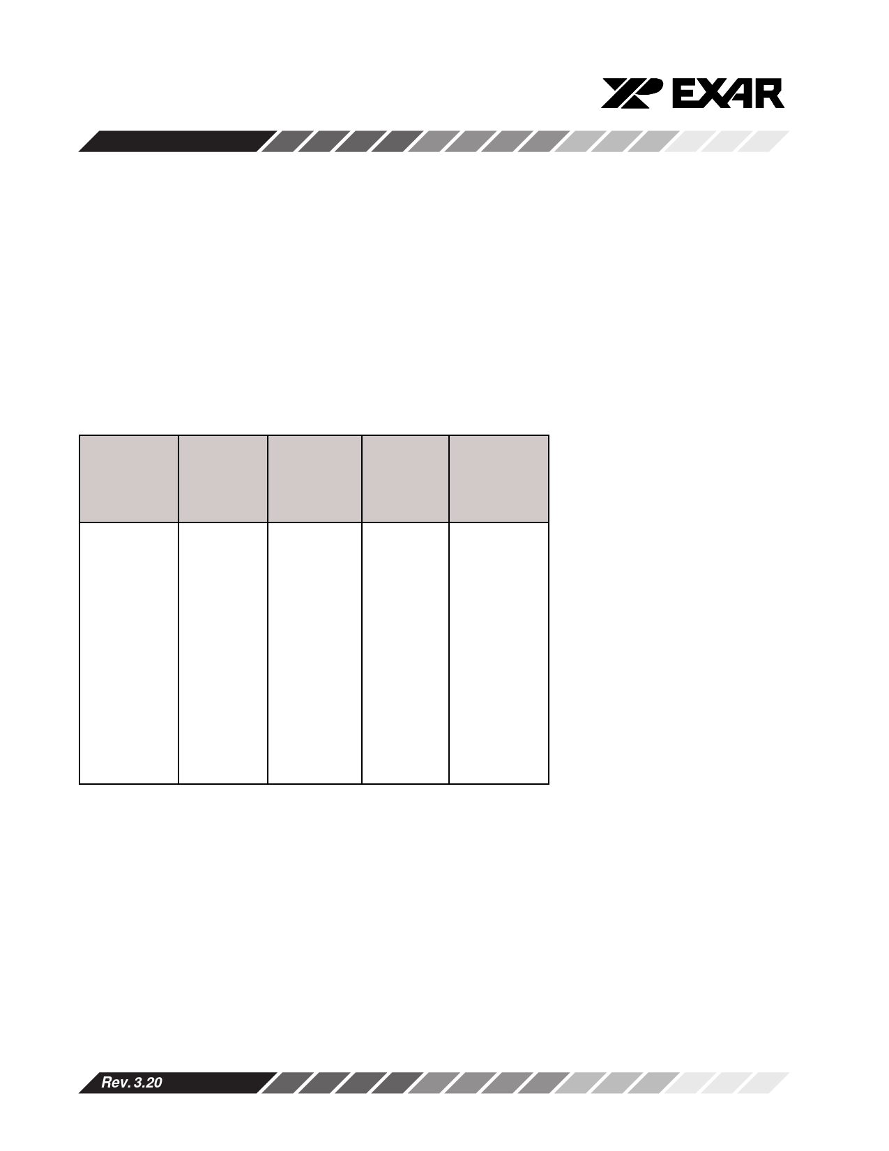
Table 5, BAUD RATE GENERATOR PROGRAMMING TABLE (1.8432 MHz CLOCK):
Output
Baud Rate
Output
16 x Clock
Divisor
(Decimal)
User
16 x Clock
Divisor
(HEX)
DLM
Program
Value
(HEX)
50
2304
900
09
110
1047
417
04
150
768
300
03
300
384
180
01
600
192
C0
00
1200
96
60
00
2400
48
30
00
4800
24
18
00
7200
16
10
00
9600
12
0C
00
19.2k
6
06
00
38.4k
3
03
00
57.6k
2
02
00
115.2k
1
01
00
DLL
Program
Value
(HEX)
00
17
00
80
C0
60
30
18
10
0C
06
03
02
01
Loop-back Mode
The internal loop-back capability allows onboard diag-
nostics. In the loop-back mode the normal modem
interface pins are disconnected and reconfigured for
loop-back internally. MCR register bits 0-3 are used
for controlling loop-back diagnostic testing. In the
loop-back mode INT enable and MCR bit-2 in the MCR
register (bits 2,3) control the modem -RI and -CD
inputs respectively. MCR signals -DTR and -RTS (bits
0-1) are used to control the modem -CTS and -DSR
inputs respectively. The transmitter output (TX) and
the receiver input (RX) are disconnected from their
associated interface pins, and instead are connected
together internally (See Figure 6). The -CTS, -DSR, -
CD, and -RI are disconnected from their normal
modem control inputs pins, and instead are connected
internally to -DTR, -RTS, INT enable and MCR bit-2.
Loop-back test data is entered into the transmit hold-
ing register via the user data bus interface, D0-D7.
The transmit UART serializes the data and passes the
serial data to the receive UART via the internal loop-
back connection. The receive UART converts the
serial data back into parallel data that is then made
Rev. 3.20
10
Share Link: 