MAX863EEE Ver la hoja de datos (PDF) - Maxim Integrated
Número de pieza
componentes Descripción
Lista de partido
MAX863EEE Datasheet PDF : 16 Pages
| |||
Dual, High-Efficiency, PFM, Step-Up
DC-DC Controller
minimum input voltages. Estimate the maximum input
currents for each output based on the minimum input
voltage and desired output power:
VOUT x IOUT
IIN,DC(MAX) ≅ 0.8 x VIN(MIN)
where 0.8 is chosen as a working value for the nominal
efficiency. The power source must be capable of deliv-
ering the sum of the maximum input currents of both
DC-DC converters.
Determine the Peak Switching Current
(Graphical Method)
The peak switching current set by RSENSE determines
the amount of energy transferred from the input on
each cycle. For 3.3V, 5V, 12V, and 24V output circuits,
the peak current can be selected using the output cur-
rent curves shown in Figures 5a–5d.
Determine the Peak Switching Current and
Inductance (Analytical Method)
The following boost-circuit equations are useful when
the desired output voltage differs from those listed in
Figure 5. They allow trading off peak current and induc-
tor value in consideration of component availability,
size, and cost.
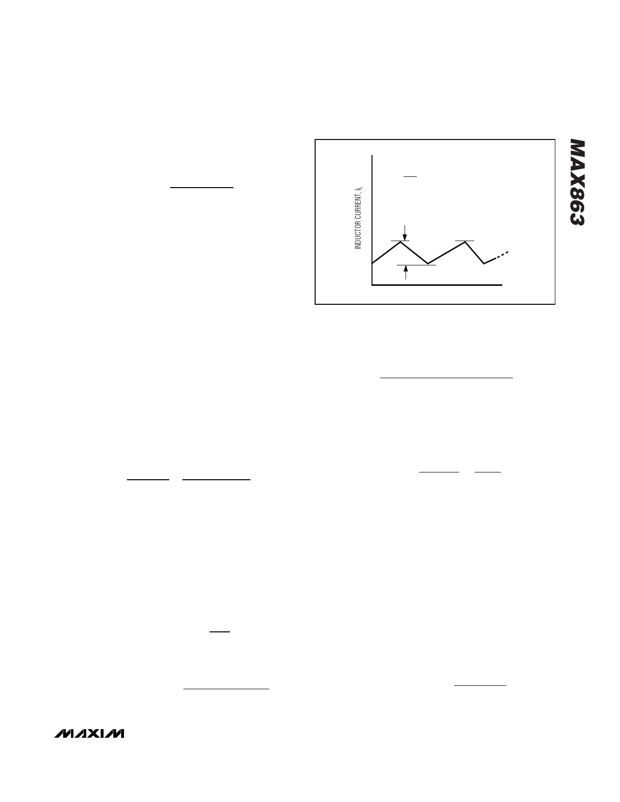
Begin by calculating the minimum allowable ratio of
inductor AC ripple current to peak current, ξMIN
(Figure 6):
ξMIN =
tOFF(MIN)
tON(MAX)
x VOUT − VIN(MIN)
VIN(MIN)
where tOFF(MIN) = 2µs and tON(MAX) = 17.5µs.
Select a value for ξ greater than ξMIN. If ξMIN is less
than 1, an acceptable choice is (ξMIN + 1) / 2. If ξMIN is
greater than 1, values between ξMIN and 2 x ξMIN are
acceptable (1.5 x ξMIN, for example). Values greater
than 1 represent designs with full-load operation in dis-
continuous-conduction mode.
Now calculate the peak switching current and induc-
tance. If ξMIN ≤ ξ ≤ 1, use:
( ) IPEAK
= IIN,DC MAX
x
2
2- ξ
For ξ ≥ 1%, use:
( ) ( ) IPEAK
=
2 x IIN,DC MAX
x
VOUT + VIN x
VOUT
ξ −1
ξMIN
=
∆IL
IPEAK
∆IL
IPEAK
t
Figure 6. Ratio of Inductor AC Ripple Current to Peak Current
The suggested inductor value is:
L≅
VOUT
-
VIN(MIN)
x tOFF(MIN)
IPEAK x ξ
Round L up to the next standard inductor value.
Choose RSENSE
The peak switching current is set by RSENSE (R1 and
R2 in Figure 2):
RSENSE ≤
VCS(MIN)
IPEAK
= 85mV
IPEAK
Verify that you’ve selected the correct RSENSE by test-
ing the prototype using the minimum input voltage
while supplying the maximum output current. If the out-
put voltage droops, then decrease the value of the cur-
rent-sense resistor and adjust the other components as
necessary.
The current-sense resistor must be a small, low-induc-
tance type such as a surface-mount metal-strip resistor.
Do not use wire-wound resistors, since their high induc-
tance will corrupt the current feedback signal. In order
to allow use of standard resistor values, round RSENSE
to the next lowest value.
The current-sense resistor’s power rating should be
higher than:
( ) V 2 CS MAX
RPOWER RATING = RSENSE
______________________________________________________________________________________ 11
Share Link: 