ACT4455 Ver la hoja de datos (PDF) - Active-Semi, Inc
Número de pieza
componentes Descripción
Lista de partido
ACT4455 Datasheet PDF : 14 Pages
| |||
ACT4455
Rev 2, 21-Nov-12
APPLICATIONS INFORMATION
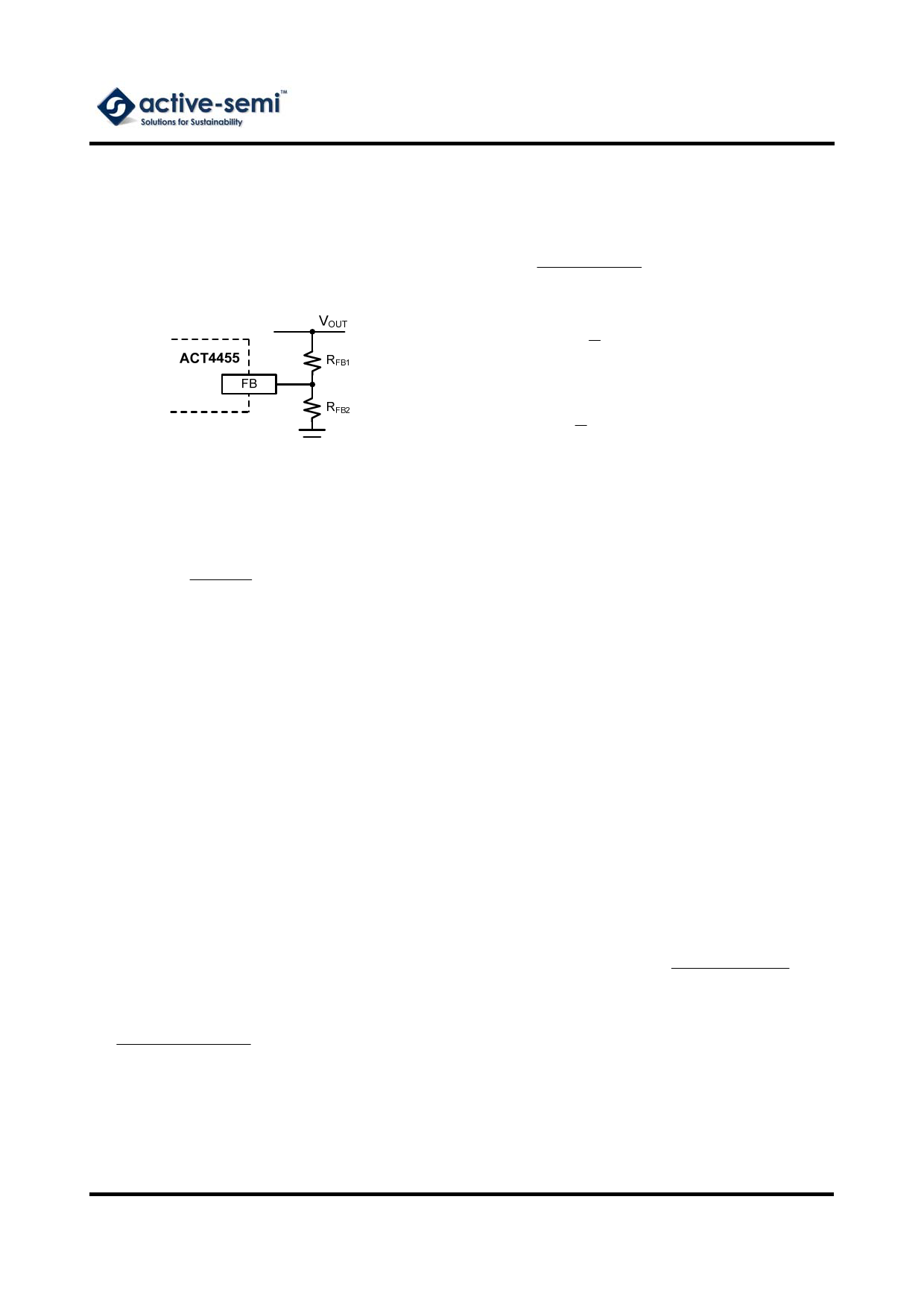
Output Voltage Setting
Figure 1:
Output Voltage Setting
With a selected inductor value the peak-to-peak
inductor current is estimated as:
( ) ILPK _PK
=
VOUT
×
VIN
V_
OUT
L ×VIN × fSW
(4)
The peak inductor current is estimated as:
1
ILPK = ILOADMAX
+
2
I
LPK
_ PK
(5)
Figure 1 shows the connections for setting the
output voltage. Select the proper ratio of the two
feedback resistors RFB1 and RFB2 based on the
output voltage. Typically, use RFB2 ≈ 10kΩ and
determine RFB1 from the following equation:
R FB 1
=
R
FB
2
⎜⎛
⎝
0
V OUT
.808
V
− 1 ⎟⎞
⎠
(1)
Over Current Protection Setting
The output over current threshold is calculated by:
IOCP1 = IOCP 2 = 116 mV / RSENSE
(2)
It is recommended that 1% or 0.5% high-accuracy
current sensing resistor is selected to achieve high-
accuracy over current protection. Two over current
protection thresholds can be different based on
different current sensing resistance.
Inductor Selection
The inductor maintains a continuous current to the
output load. This inductor current has a ripple that is
dependent on the inductance value:
Higher inductance reduces the peak-to-peak ripple
current. The trade off for high inductance value is
the increase in inductor core size and series
resistance, and the reduction in current handling
capability. In general, select an inductance value L
based on ripple current requirement:
( ) L =
VOUT
×
VIN
V_
OUT
(3)
V f I K IN SW LOADMAX RIPPLE
where VIN is the input voltage, VOUT is the output
voltage, fSW is the switching frequency, ILOADMAX is
the maximum load current, and KRIPPLE is the ripple
factor. Typically, choose KRIPPLE = 30% to
correspond to the peak-to-peak ripple current being
30% of the maximum load current.
The selected inductor should not saturate at ILPK.
The maximum output current is calculated as:
IOUTMAX
=
I_
LIM
1
2
I
LPK
_ PK
(6)
ILIM is the internal current limit, which is typically
6.5A, as shown in Electrical Characteristics Table.
Input Capacitor
The input capacitor needs to be carefully selected
to maintain sufficiently low ripple at the supply input
of the converter. A low ESR capacitor is highly
recommended. Since large current flows in and out
of this capacitor during switching, its ESR also
affects efficiency.
The input capacitance needs to be higher than
10µF. The best choice is the ceramic type,
however, low ESR tantalum or electrolytic types
may also be used provided that the RMS ripple
current rating is higher than 50% of the output
current. The input capacitor should be placed close
to the IN and G pins of the IC, with the shortest
traces possible. In the case of tantalum or
electrolytic types, they can be further away if a
small parallel 0.1µF ceramic capacitor is placed
right next to the IC.
Output Capacitor
The output capacitor also needs to have low ESR to
keep low output voltage ripple. The output ripple
voltage is:
VRIPPLE
= IOUTMAX K R RIPPLE ESR
+
28
VIN
× fSW 2 LCOUT
(7)
Where IOUTMAX is the maximum output current,
KRIPPLE is the ripple factor, RESR is the ESR of the
output capacitor, fSW is the switching frequency, L is
the inductor value, and COUT is the output
capacitance. In the case of ceramic output
capacitors, RESR is very small and does not
contribute to the ripple. Therefore, a lower
capacitance value can be used for ceramic type. In
the case of tantalum or electrolytic capacitors, the
ripple is dominated by RESR multiplied by the ripple
Innovative PowerTM
-6-
www.active-semi.com
Copyright © 2012 Active-Semi, Inc.
Share Link: 