AD2S100 Ver la hoja de datos (PDF) - Analog Devices
Número de pieza
componentes Descripción
Lista de partido
AD2S100 Datasheet PDF : 12 Pages
| |||
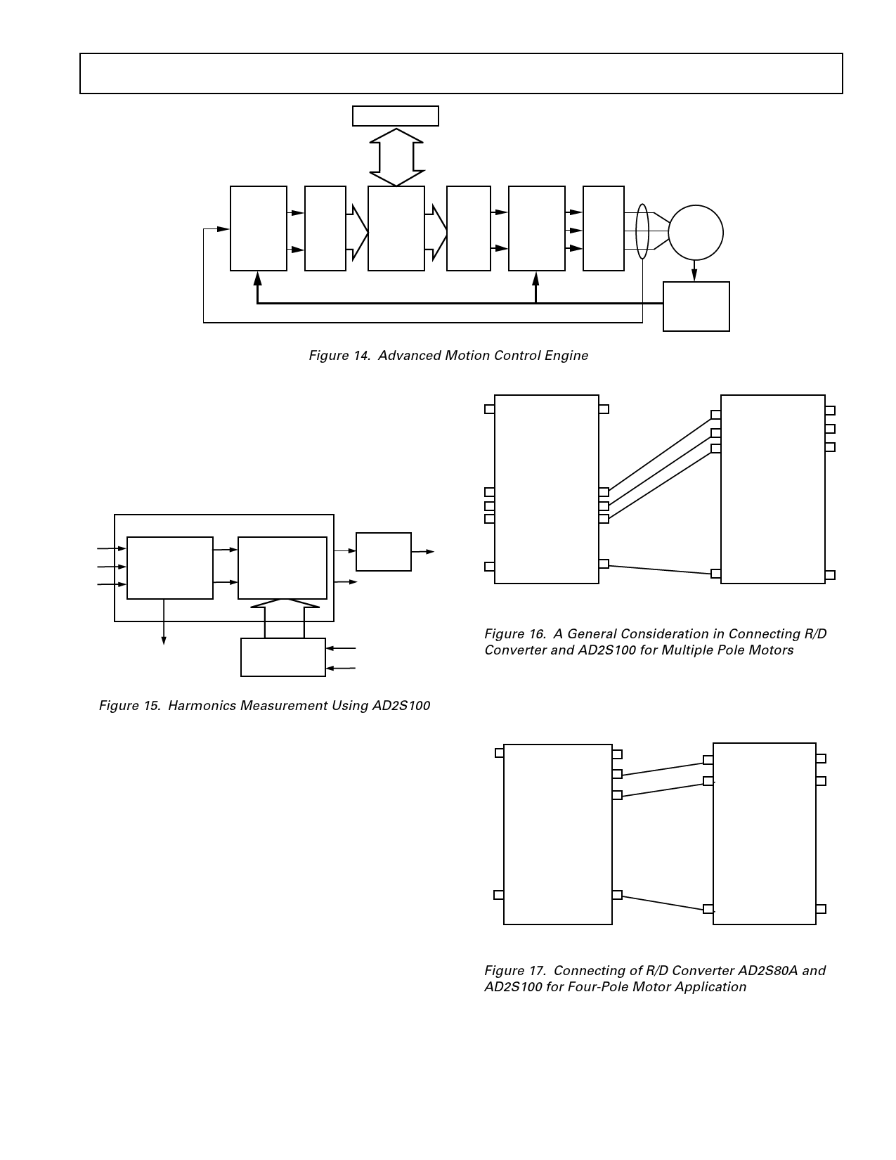
HOST COMPUTER
AD2S100
VECTOR
COPROCESSOR
ADC
DAC
VECTOR
COPROCESSOR
AD2S100
AD7874
ADSP-2101/
ADSP-2105
DAC-8412
AD2S100
INV
+
PWM
INDUCTION
MOTOR
ia, ib, ic
θ
AD2S80A
R/D
CONVERTER
Figure 14. Advanced Motion Control Engine
The magnitude of the n-th harmonic as well as the fundamental
component in the power line is represented by the output of the
low-pass filter, ak. In concert with magnitude of the harmonic
the AD2S100 homopolar output will indicate whether the
three phases are balanced or not. For more details about this
application, refer to the related application note listed in the
bibliography.
AD2S100
Va
Vd
Vd1 LOW PASS ak
Vb
TWO-TO-THREE
CLARK
e–jφ PARK
FILTER
Vc
TRANSFORMATION Vq TRANSFORMATION Vq1
AD2S80A
MSB
MSB-1
.
.
.
MSB – (n–1)
.
.
.
LSB + (n–1)
n = POLES
.
.
.
.
12,14 OR 16-BIT RESOLUTION MODE
AD2S100
MSB
MSB-1
MSB-2
.
.
.
.
.
.
.
LSB
HOMOPOLAR
OUTPUT
12-BIT UP/DOWN
COUNTER
PULSE INPUTS
DIRECTION
Figure 15. Harmonics Measurement Using AD2S100
MULTIPLE POLE MOTORS
For multi-pole motor applications where a single speed resolver
is used, the AD2S100 input has to be configured to match the
electrical cycle of the resolver with the phasing of the motor
windings. The input to the AD2S100 is the output of a resolver-
to-digital converter, e.g., AD2S80A series. The parallel output
of the converter needs to be multiplied by 2n–1, where
n = the number of pole parts of the motor. In practice this is
implemented by shifting the parallel output of the converter left
relative to the number of pole pairs.
Figure 16 shows the generic configuration of the AD2S80A with
the AD2S100 for a motor with n pole pairs. The MSB of the
AD2S100 is connected to MSB-(n-1) bit of the AD2S80A digi-
tal output, MSB-1 bit to MSB-(n-2) bit, . . ., LSB bit to LSB
bit of AD2S80A, etc.
Figure 16. A General Consideration in Connecting R/D
Converter and AD2S100 for Multiple Pole Motors
Figure 17 shows the AD2S80A configured for use with a four
pole motor, where n = 2. Using the formula described the MSB
is shifted left once
AD2S80A
AD2S100
(MSB) BIT1
MSB
BIT2
MSB-1
.
.
.
.
.
.
.
.
.
.
.
.
.
.
.
BIT13
(LSB) BIT14
.
.
.
.
LSB
14-BIT RESOLUTION MODE
Figure 17. Connecting of R/D Converter AD2S80A and
AD2S100 for Four-Pole Motor Application
REV. A
–11–
Share Link: 