L292(1993) Ver la hoja de datos (PDF) - STMicroelectronics
Número de pieza
componentes Descripción
Lista de partido
L292 Datasheet PDF : 12 Pages
| |||
L292
It is possible to verify that the L292 works in "closed-
loop" conditions during the entire motor current
rise-time: the voltage at pin 7 inverting input of the
error amplifier) is locked to the reference voltage
VR, present at the non-inverting input of the same
amplifier.
The previous linear analysis is correct for this ex-
ample.
Descresing the ξ value, the rise-time of the current
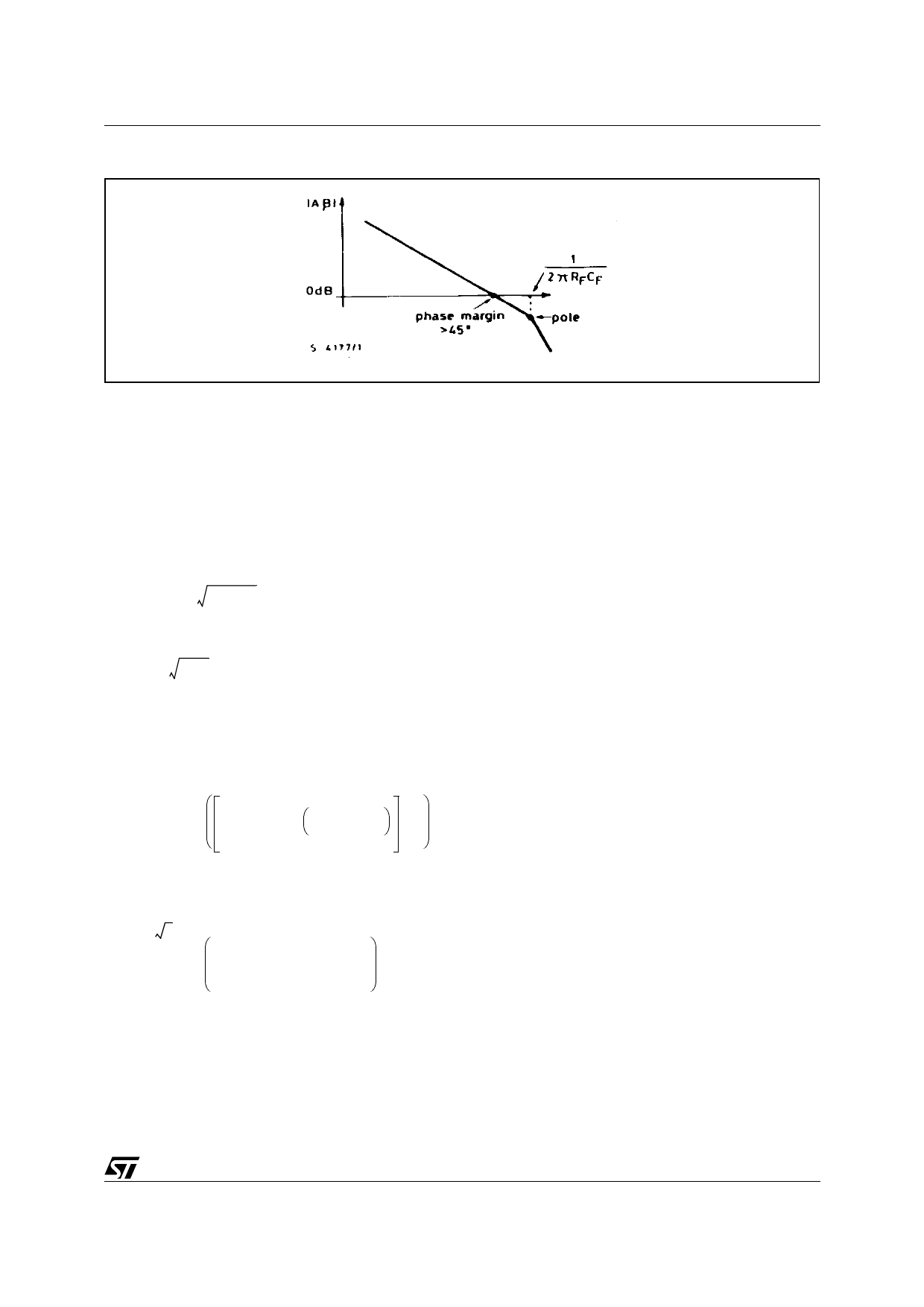
decreases. But for a good stability, from relationship
(6), the maximum value of ξ is:
ξmin
=
1
2 4√
2
(phase margin = 45°)
b) Large signal reponse
The large step signal response is limited by slew-
rate and inductive load.
In this case, during the rise-time of the motor
current, The L292 works is open-loop condition.
CLOSED LOOP SYSTEM BANDWIDTH.
A good choice for x is the value 1 / √2. In this case :
IM
VI
(s)
=
0.044
Rs
1 + s RF CF
1 + 2s RF CF + 2s 2 RF 2 CF 2
(8)
The module of the transfer function is :
|
IM
VI
|
=
0.044
Rs
2
√1+ω2RF2CF2
√[ ( 1+2ωRFCF)2+1]•[(1−2ωRFCF)2+1 ]
(9)
The cutoff frequency is derived by the expression (9) by putting
which :
|
IM
VI
|
=
0.707
•
0.044
Rs
(−3 dB),
from
ωT
=
0.9
RF CF
fT
=
0.9
2π RF CF
9/12
Share Link: 