LV7107M Ver la hoja de datos (PDF) - SANYO -> Panasonic
Número de pieza
componentes Descripción
Lista de partido
LV7107M Datasheet PDF : 35 Pages
| |||
LV7107M
Cautions for Use
1. Drive capacity of video driver
Line and component outputs can drive two systems through capacitive coupling.
Scart output can drive one system only through DC coupling.
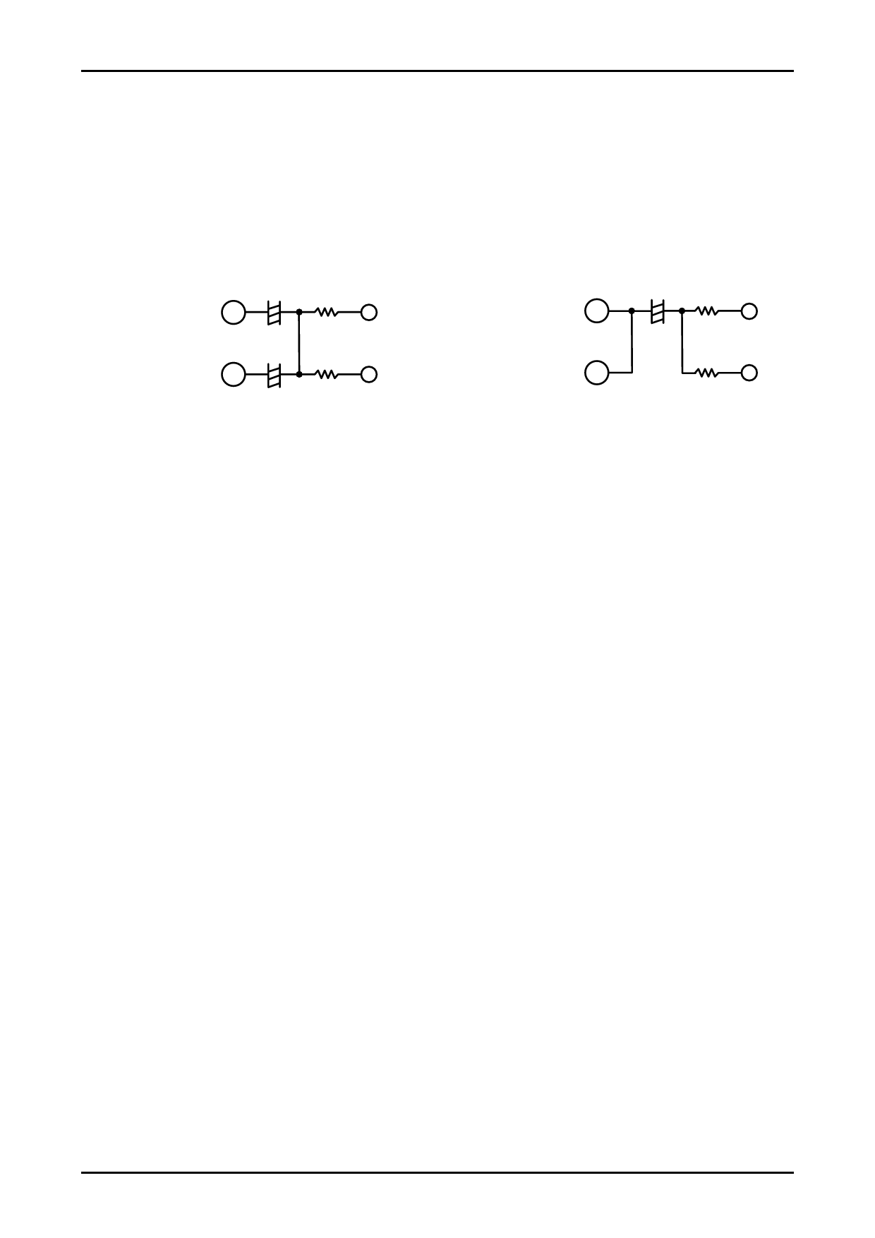
2. Application not using the SAG correction function in the video driver with SAG correction
When the SAG correction function is not to be used in the video driver with SAG correction, short-circuit output and
correction pins for output through capacitive coupling.
Application using SAG correction function
Application without using SAG correction function
Video output pin
SAG correction pin
+
75Ω
100µF
+
75Ω
22µF
Video output pin
SAG correction pin
+
75Ω
1000µF
75Ω
3. Treatment of the pin when Audio RF_MOD output is not used
When RF MOD OUT (Pin76) is not used, it is recommended to pull up the ALC filter pin (pin77) to VCC (11.6V).
4. Audio Mute
This IC incorporates a mute transistor to reduce the POP noise of audio output when power is turned ON/OFF.
Mute control can be made by serial control.
5. Resistor to limit the Audio input
When the large signal is input in the input pin with power OFF, cross-talke between input and output occurs through
the protective diode and parasitic elements. Because of the structure of LSI, such cross-talke is difficult to avoid. If
cross-talk at a time of power OFF presents a problem, the cross-talk amount can be reduced by inserting the limiting
resistor in the input. In this case, the input signal level changes depending on the resistance value. Determine the
constant while taking both the cross-talk amount and input level into account.
6. Pin treatment when external control is not to be used
When external control pins (Pins 13, 36, and 38) are not used, pull-down to GND is recommended.
7. Pin treatment of N.C pin
It is recommended to connect N.C. pins (Pins 67, 68, 69, and 70) directly to the GND.
8. Audio 9V_REG pin external capacitance
Use the Audio 9V_REG pins (pins 57 and 66) external capacitance of 10µF or more and with the equivalent series
resistance component of 7Ω or less.
9. Power application and disconnection sequences
The recommended power application sequence to this IC is VCC_ALL5V (Pin42) → VCC5V (Pins 6, 8, 25, 40, 84
and 94), VCC11.6V (Pin46). (No particular order is established between VCC5V and VCC11.6V.) It is recommended
to reverse the above sequence when power supply is turned OFF.
No.A0913-11/35
Share Link: 