IRFP23N50L Ver la hoja de datos (PDF) - International Rectifier
Número de pieza
componentes Descripción
Lista de partido
IRFP23N50L Datasheet PDF : 9 Pages
| |||
IRFP23N50L
10
1
D = 0.50
0.1
0.20
0.10
0.05
0.02
0.01
0.01
0.001
0.00001
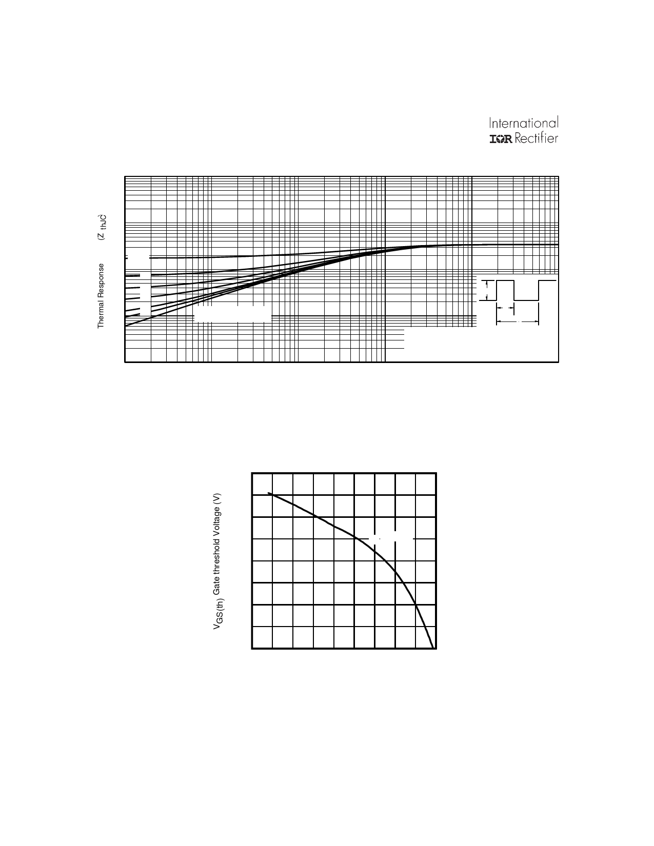
P DM
SINGLE PULSE
(THERMAL RESPONSE)
t1
t2
Notes:
1. Duty factor D =
t1/ t 2
2. Peak T J = P DM x Z thJC + T C
0.0001
0.001
0.01
0.1
1
t1, Rectangular Pulse Duration (sec)
Fig 12. Maximum Effective Transient Thermal Impedance, Junction-to-Case
5.0
4.5
4.0
3.5
ID = 250µA
3.0
2.5
2.0
1.5
1.0
-75 -50 -25 0
25 50 75 100 125 150
TJ , Temperature ( °C )
Fig 13. Threshold Voltage vs. Temperature
6
www.irf.com
Share Link: 