RF2642PCBA41X Ver la hoja de datos (PDF) - RF Micro Devices
Número de pieza
componentes Descripción
Lista de partido
RF2642PCBA41X Datasheet PDF : 10 Pages
| |||
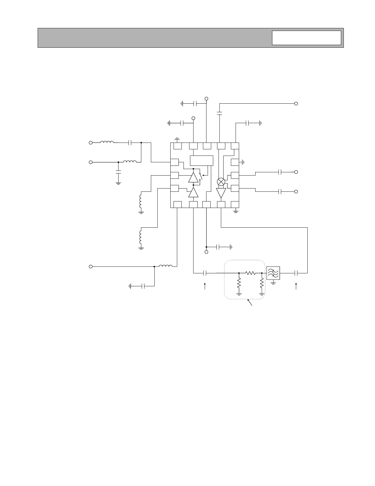
RF2642
Application Schematic
NOTE:
1. 1 nF: DC blocking capacitor - this can be removed if the filter is DC blocked.
2. T-attenuator - this is to control the overall gain of the upconverter + PA driver. This can be set to zero if it is desired.
VCC
10 nF
LO IN
Gain Select
1 nF
PA OUT
VPA2
3.9 nH
1 nF
8.2 nH
10 nF
Formed by stripline
RF GND2
Variable2
10 nF
1 nF
1
16 15 14 13
Logic
2
Control
12
3
11
IF+
1 nF
4
10
5
67
8
9
IF-
1 nF
2642400B
Formed by stripline
RF GND1
Variable1
VPA1
8.2 nH
10 nF
10 nF
PD
1 nF
See Note 1
5.1 Ω
RF SAW
Filter
820 Ω 820 Ω
1 nF
See Note 1
See Note 2
Rev A8 060925
6-53
Share Link: 