MAX1574 Ver la hoja de datos (PDF) - Maxim Integrated
Número de pieza
componentes Descripción
Lista de partido
MAX1574 Datasheet PDF : 9 Pages
| |||
180mA, 1x/2x, White LED Charge Pump
in 3mm x 3mm TDFN
Detailed Description
The MAX1574 charge pump drives up to three white
LEDs with regulated constant current for uniform inten-
sity. By utilizing adaptive 1x/2x charge-pump modes
and very-low-dropout current regulators, it achieves
180mA output drive capability and high efficiency over
the 1-cell lithium-battery input voltage range. Fixed-fre-
quency switching of 1MHz allows for tiny external com-
ponents, and the regulation scheme is optimized to
ensure low EMI and low input ripple.
1x to 2x Switchover
When VIN is higher than VOUT, the MAX1574 operates in
1x mode and VOUT is pulled up to VIN. The internal cur-
rent regulators regulate the LED current. As VIN drops,
VLED_ eventually falls below the switchover threshold of
130mV, and the MAX1574 starts switching in 2x mode.
When the input voltage rises above VOUT by approxi-
mately 50mV, the MAX1574 switches back to 1x mode.
Soft-Start
The MAX1574 includes soft-start circuitry to limit inrush
current at turn-on. When starting up, the output capacitor
is charged directly from the input with a ramped current
source (with no charge-pump action) until the output volt-
age approaches the input voltage. Once this occurs, the
charge pump determines if 1x or 2x mode is required. In
the case of 1x mode, the soft-start is terminated and nor-
mal operation begins. During the soft-start time, the out-
put current is set to 5% of the maximum set by RSET. In
the case of 2x mode, soft-start operates until the lowest of
LED1 to LED3 reaches regulation. If an overload condi-
tion occurs, soft-start repeats every 2.1ms. If the output is
shorted to ground, the output current is limited by the
MAX1574 switching technique.
Setting the Output Current
The LED current at full brightness is set by a resistor,
RSET, as follows:
RSET
=
0.6V × 393
ILED _
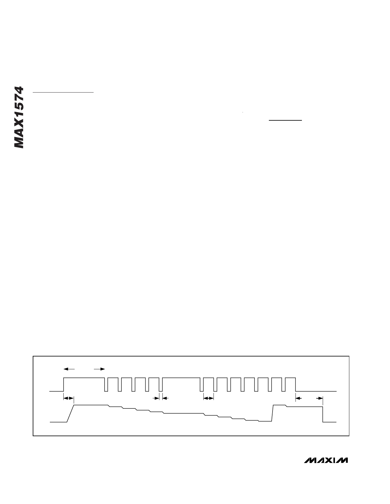
EN Dimming Control
When the LEDs are enabled by driving EN high, the
MAX1574 goes through soft-start, bringing the LED cur-
rent up to ILED_. Dimming is then done by pulsing EN
low (500ns to 500µs pulse width). Each pulse reduces
the LED current by 10%, so after one pulse the LED cur-
rent is 0.9 x ILED. The tenth pulse reduces the current by
5%, so the ILED_ current reduces from 0.1 x ILED_ to 0.05
x ILED. The eleventh pulse sets the LED current back to
ILED_. Figure 1 shows a timing diagram for EN.
If dimming control is not required, EN works as a simple
on/off control. Drive EN high to enable the LEDs, or
drive EN low for shutdown.
Shutdown Mode
When EN is held low for 2ms or longer, the MAX1574
is shut down and put in a low-current mode. OUT is
internally pulled to GND with 5kΩ during shutdown.
Overvoltage Protection
If any LED fails as an open circuit, the output voltage is
limited to about 5V by gating on/off the charge pump.
If any LED_ is floating or grounded, the MAX1574 oper-
ates in the same overvoltage-protection mode. To avoid
overvoltage-protection mode when using fewer than
three LEDs, connect any unused LED_ to IN (Figure 3).
Thermal Shutdown
The MAX1574 includes a thermal-limit circuit that shuts
down the IC at approximately +160°C. The part turns on
after the IC cools by approximately 20°C.
INITIAL tHI
0
≥ 50µs
EN
tSOFT-START
100%
ILED_
SHDN
12345
tLO
90%
80%
70%
500ns TO 500µs
60% 50%
6 7 8 9 10 11
tHI
≥ 500ns
40% 30% 20% 10% 5%
tSHDN
100% 90% 2ms (typ)
SHDN
Figure 1. EN Timing Diagram
6 _______________________________________________________________________________________
Share Link: 