HIP2106IB Ver la hoja de datos (PDF) - Intersil
Número de pieza
componentes Descripción
Lista de partido
HIP2106IB Datasheet PDF : 8 Pages
| |||
HIP2106
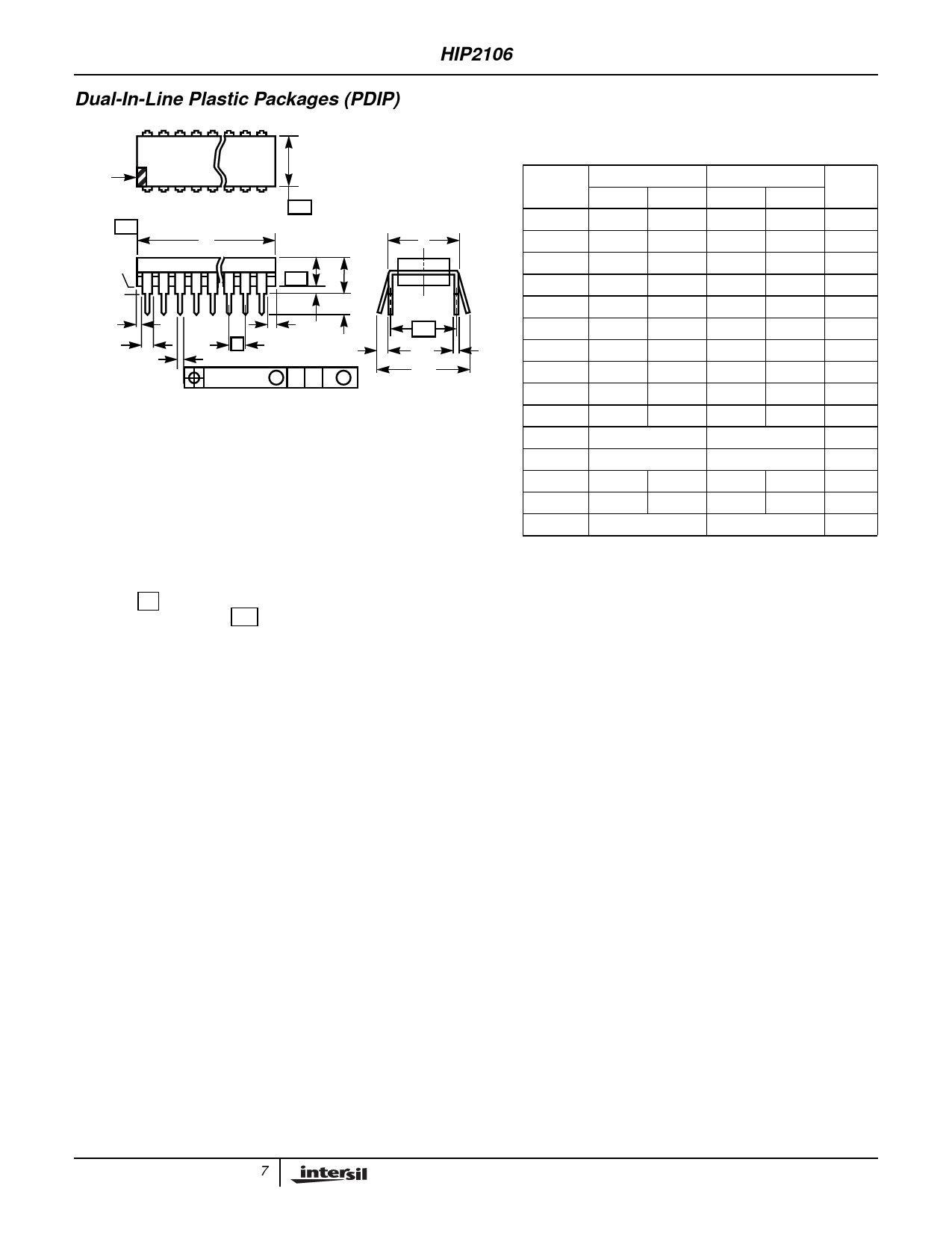
Dual-In-Line Plastic Packages (PDIP)
INDEX
AREA
N
12 3
E1
N/2
-B-
-A-
D
E
BASE
PLANE
SEATING
PLANE
-C- A2 A
L
CL
D1
D1
A1
eA
B1
e
B
eC
C
0.010 (0.25) M C A B S
eB
NOTES:
1. Controlling Dimensions: INCH. In case of conflict between
English and Metric dimensions, the inch dimensions control.
2. Dimensioning and tolerancing per ANSI Y14.5M-1982.
3. Symbols are defined in the “MO Series Symbol List” in Section
2.2 of Publication No. 95.
4. Dimensions A, A1 and L are measured with the package seated
in JEDEC seating plane gauge GS-3.
5. D, D1, and E1 dimensions do not include mold flash or
protrusions. Mold flash or protrusions shall not exceed 0.010
inch (0.25mm).
6. E and eA are measured with the leads constrained to be
perpendicular to datum -C- .
7. eB and eC are measured at the lead tips with the leads
unconstrained. eC must be zero or greater.
8. B1 maximum dimensions do not include dambar protrusions.
Dambar protrusions shall not exceed 0.010 inch (0.25mm).
9. N is the maximum number of terminal positions.
10. Corner leads (1, N, N/2 and N/2 + 1) for E8.3, E16.3, E18.3,
E28.3, E42.6 will have a B1 dimension of 0.030 - 0.045 inch
(0.76 - 1.14mm).
E8.3 (JEDEC MS-001-BA ISSUE D)
8 LEAD DUAL-IN-LINE PLASTIC PACKAGE
INCHES
MILLIMETERS
SYMBOL MIN
MAX
MIN
MAX NOTES
A
-
0.210
-
5.33
4
A1
0.015
-
0.39
-
4
A2
0.115 0.195 2.93
4.95
-
B
0.014 0.022 0.356 0.558
-
B1
0.045 0.070 1.15
1.77 8, 10
C
0.008 0.014 0.204 0.355
-
D
0.355 0.400 9.01 10.16
5
D1
0.005
-
0.13
-
5
E
0.300 0.325 7.62
8.25
6
E1
0.240 0.280 6.10
7.11
5
e
0.100 BSC
2.54 BSC
-
eA
0.300 BSC
7.62 BSC
6
eB
-
0.430
-
10.92
7
L
0.115 0.150 2.93
3.81
4
N
8
8
9
Rev. 0 12/93
7
Share Link: 