LTC1535(1999) Ver la hoja de datos (PDF) - Linear Technology
Número de pieza
componentes Descripción
Lista de partido
LTC1535 Datasheet PDF : 12 Pages
| |||
LTC1535
APPLICATIO S I FOR ATIO
Isolation Barrier and Sampled Communication
The LTC1535 uses the SW-28 isolated lead frame package
to provide capacitive isolation barrier between the logic
interface and the RS485 driver/receiver pair. The barrier
provides 2500VRMS of isolation. Communication between
the two sides uses the isolation capacitors in a multiplexed
way to communicate full-duplex data across this barrier.
The data is sampled and encoded before transmitting
across the isolation barrier, which will add sampling jitter
and delay to the signals. The sampling jitter is approxi-
mately 250ns with a nominal delay of 600ns. At 250kBd
rate, this represents 6.2% total jitter. The nominal DE
signal to the driver output delay is 875ns ±125ns, which is
longer due to the encoding. Communication start-up time
is approximately 1µs to 2µs. A time-out fault will occur if
communication from the isloated side fails. Faults can be
monitored on the RE pin.
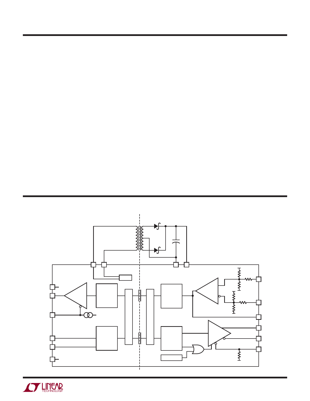
Push-Pull DC/DC Converter
The powered side contains a full-bridge open-loop driver,
optimized for use with a single primary and center-tapped
secondary transformer. Figure 9 shows the DC/DC con-
verter in a configuration that can deliver up to to 100mA of
current to the isolated side using a Coiltronics CTX02-
14659 transformer.
Because the DC/DC converter is open-loop, care in choos-
ing low impedance parts is important for good regulation.
Care must also be taken to not exceed the VCC2 recom-
mended maximum voltage of 7.5V when there is very light
loading. The isolated side contains a low voltage detect
circuit to ensure that communication across the barrier
will only occur when there is sufficient isolated supply
voltage. If the output of the DC/DC converter is over-
loaded, the supply voltage will trip the low voltage detec-
tion at 4.2V. For higher voltage stand-off, the Coiltronics
CTX02-14608 transformer may be used.
**
CTX02-14659
1/2 BAT54C
2
ILOAD IEXT
IVCC2
+
10µF
VCC +
1
10µF
1
4
1
2
VCC ST1
GND
LOGIC COMMON
1
3
ST2
400kHz
1/2 BAT54C
2
11
GND2
14
VCC2
1535 F09
FLOATING RS485 COMMON ** TRANSFORMER
COILTRONICS (561) 241-7876
2
Figure 9
VCC2 vs ILOAD
8
6
VCC = 5.5V
4
VCC = 5V
VCC = 4.5V
2
0
0
50
100
150
TOTAL LOAD CURRENT, ILOAD (mA)
1535 F09a
7
Share Link: 