ACT6358(2007) Ver la hoja de datos (PDF) - Active-Semi, Inc
Número de pieza
componentes Descripción
Lista de partido
ACT6358 Datasheet PDF : 10 Pages
| |||
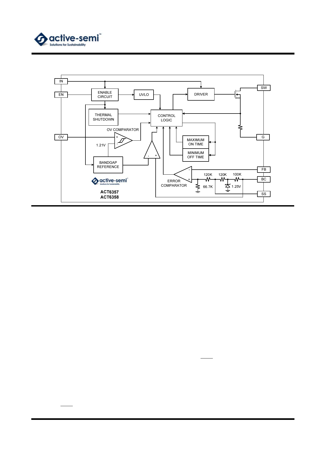
FUNCTIONAL BLOCK DIAGRAM
ACT6357/ACT6358
Rev PrB, 30-Aug-07
Control Scheme
The ACT6357 and ACT6358 use a minimum off-
time, current-mode control scheme to achieve
excellent performance under high duty-cycle oper-
ating conditions. This control scheme initiates a
switching cycle only when needed to maintain out-
put voltage regulation, resulting in very high effi-
ciency operation.
During each switching cycle, the N-channel power
MOSFET turns on, increasing the inductor current.
The switching cycle terminates when either the in-
ductor current reaches the current limit (500mA for
the ACT6357, 1A for the ACT6358) or when the
cycle lasts longer than the maximum on-time of
4µs. Once the MOSFET turns off, it remains off for
at least the minimum off-time of 320ns, then an-
other switching begins when the error comparator
detects that the output is falling out of regulation
again.
Soft-Start
The ACT6357 and ACT6358 include a programma-
ble soft-start function, which can be used to opti-
mize an application between start-up time and
start-up inrush current. Soft start is achieved by
connecting a capacitor CSS between the SS pin and
G. The soft start duration can be calculated from
the following equation:
CSS
tSS
5 μF
s
where tSS is the required soft start duration. In a
typical application, use 0.1µF to generate 20ms soft
start time.
Over Voltage Protection
Both the ACT6357 and ACT6358 include internal
over-voltage protection circuitry that monitors the
OV pin voltage. Over-voltage protection is critical
when one of the LEDs in the LED string fails as an
open circuit. When this happens the feedback volt-
age drops to zero, and the control switches at maxi-
mum on time causing the output voltage to keep
rising until it exceeds the maximum voltage rating of
the power MOSFET. The ACT6357 and ACT6358's
over-voltage protection detects this condition and
switching ceases if the voltage at the OV pin
reaches 1.21V.
To set the maximum output voltage, connect a re-
sistor divider from the output node to G, with center
tap at OV, and select the two resistors with the fol-
lowing equation:
ROV2
ROV1
1V.2O1VV
1
where VOV is the over voltage detection threshold,
ROV1 is the resistor between OV and G, and ROV2 is
the resistor from the output to the OV pin. As a first
estimate, the OV threshold can often be set to 4V
times the number of LEDs in the string.
Innovative Products. Active Solutions.
-5-
www.active-semi.com
Copyright © 2007 Active-Semi, Inc.
Share Link: 