AX88772 Ver la hoja de datos (PDF) - Unspecified
Número de pieza
componentes Descripción
Lista de partido
AX88772 Datasheet PDF : 43 Pages
| |||
AX88772
USB to 10/100 Fast Ethernet/HomePNA Controller
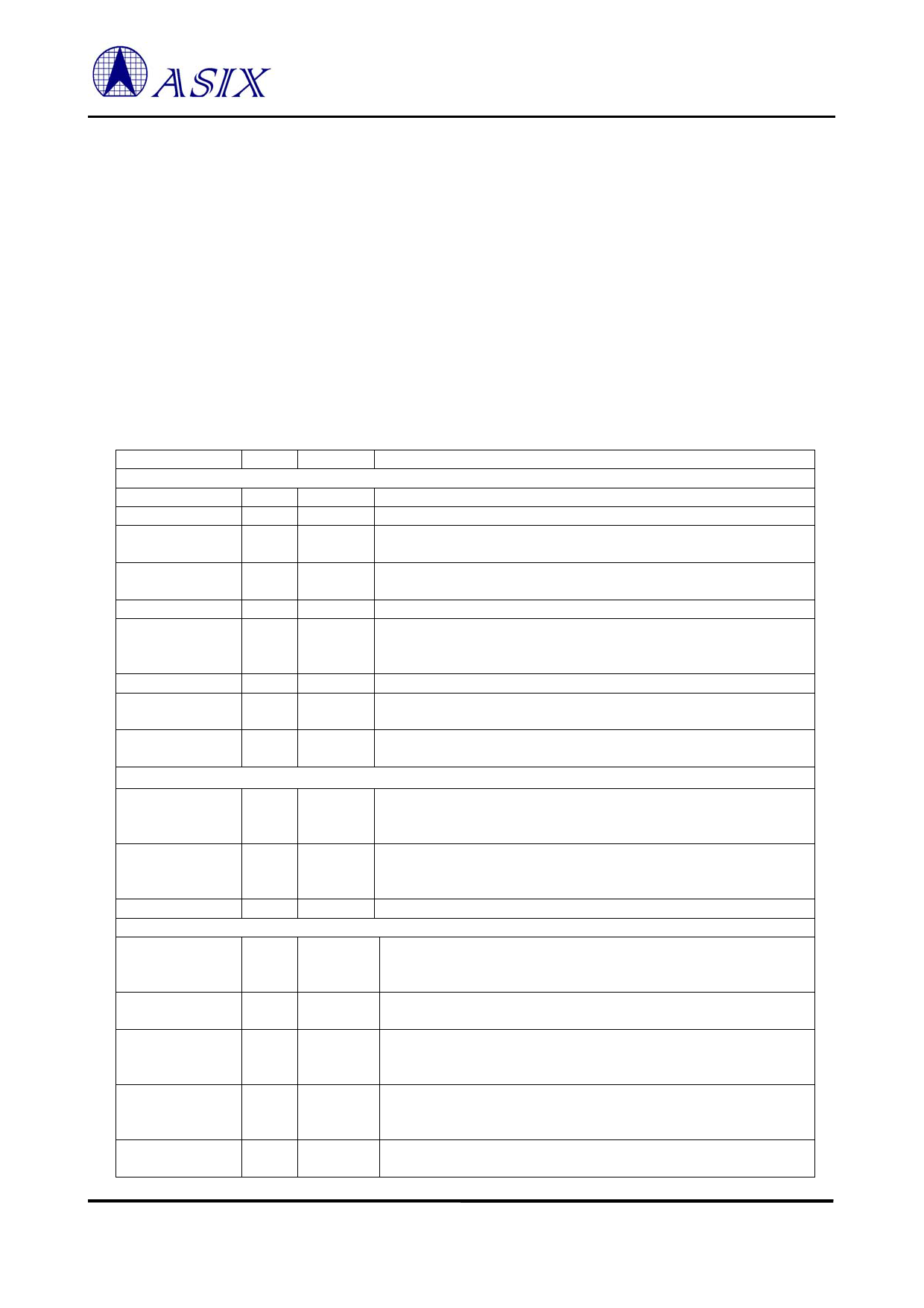
2.0 Signal Description
The following abbreviations apply to the following pin description table.
I2 Input, 2.5V with 3.3V tolerant
I3 Input, 3.3V
I5 Input, 3.3V with 5V tolerant
O2 Output, 2.5V with 3.3V tolerant
O3 Output, 3.3V
O5 Output, 3.3V with 5V tolerant
B Bi-directional I/O
B2 Bi-directional I/O, 2.5V with 3.3V tolerant
B5 Bi-directional I/O, 3.3V with 5V tolerant
PU Internal Pull Up (75K)
PD Internal Pull Down (75K)
P Power Pin
S Schmitt Trigger
Pin Name
DP
DM
DPRS
DMRS
VBUS
XIN12M
XOUT12M
RREF
RPU
MDC
MDIO
MDINT
RX_CLK
RXD [3:0]
RX_DV
RX_ER
COL
Table 1: Pinout Description
Type
B
B
B
B
I5/PD/S
I3
O3
I
I
O2
B2/PU
I2/PU
I2
I2
I2
I2
I2
Pin No
Pin Description
USB Interface
32 USB 2.0 data positive pin.
31 USB 2.0 data negative pin.
36 USB 1.1 data positive pin. Please connect to DP through a 39ohm
(+/-1%) serial resistor.
35 USB 1.1 data negative pin. Please connect to DM through a 39ohm
(+/-1%) serial resistor.
10 VBUS pin input. Please connect to USB bus power.
26 12Mhz crystal or oscillator clock input. This clock is needed for USB
PHY transceiver to operate. The recommended operating frequency
range is 12.000800Mhz ~12.004800Mhz.
27 12Mhz crystal or oscillator clock output.
30 For USB PHY’s internal biasing. Please connect to AGND through a
12.1Kohm (+/-1%) resistor.
34 For USB PHY’s internal biasing. Please connect to AVDD3 (3.3V)
through a 1.5Kohm (+/-5%) resistor.
Station Management Interface
121 Station Management Data Clock output. The timing reference for
MDIO. All data transfers on MDIO are synchronized to the rising edge
of this clock. The frequency of MDC is 1.5MHz.
120 Station Management Data Input/Output. Serial data input/output
transfers from/to the PHYs. The transfer protocol conforms to the
IEEE 802.3u MII spec.
117 Station Management Interrupt input.
MII Interface
104 Receive Clock. RX_CLK is received from PHY to provide timing
reference for the transfer of RXD [7:0], RX_DV, and RX_ER signals
on receive direction of MII interface.
110, 109, Receive Data. RXD [3:0] is driven synchronously with respect to
108, 107 RX_CLK by PHY.
105 Receive Data Valid. RX_DV is driven synchronously with respect to
RX_CLK by PHY. It is asserted high when valid data is present on
RXD [3:0].
106 Receive Error. RX_ER is driven synchronously with respect to
RX_CLK by PHY. It is asserted high for one or more RX_CLK
periods to indicate to the MAC that an error has detected.
116 Collision Detected. COL is driven high by PHY when the collision is
detected.
6
ASIX ELECTRONICS CORPORATION
Share Link: 