RTL8201CP Ver la hoja de datos (PDF) - Realtek Semiconductor
Número de pieza
componentes Descripción
Lista de partido
RTL8201CP
Realtek Semiconductor

RTL8201CP Datasheet PDF : 38 Pages
| |||
RTL8201CP
Datasheet
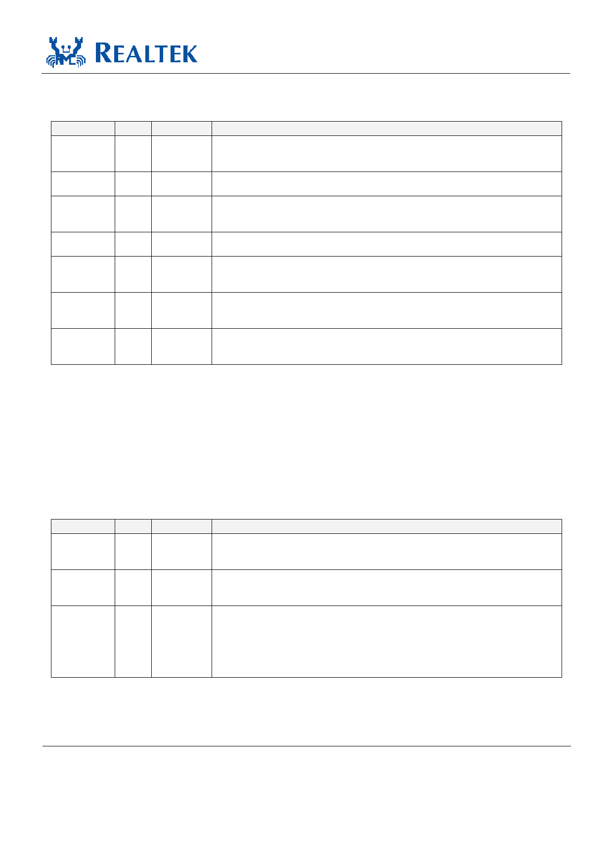
5.5. Device Configuration Interface
Name Type
ISOLATE
I
RPTR
I
SPEED
LI
DUPLEX LI
ANE
LI
LDPS
I
MII/SNIB LI/O
Pin No.
43
40
39
38
37
41
44
Table 5. Device Configuration Interface
Description
Set high to isolate the RTL8201CP from the MAC. This will also isolate the MDC/MDIO
management interface. In this mode, the power consumption is minimum. This pin can be
directly connected to GND or VCC.
Set high to put the RTL8201CP into repeater mode. This pin can be directly connected
to GND or VCC.
This pin is latched to input during a power on or reset condition. Set high to put
the RTL8201CP into 100Mbps operation. This pin can be directly connected to GND or
VCC.
This pin is latched to input during a power on or reset condition. Set high to
enable full duplex. This pin can be directly connected to GND or VCC.
This pin is latched to input during a power on or reset condition. Set high to
enable Auto-negotiation mode, set low to force mode. This pin can be directly
connected to GND or VCC.
Set high to put the RTL8201CP into LDPS mode. This pin can be directly connected
to GND or VCC. See 7.7 Power Down, Link Down, Power Saving, and Isolation
Modes, page 20, for more information.
This pin is latched to input during a power on or reset condition. Pull high to set
the RTL8201CP into MII mode operation. Set low for SNI mode. This pin can be
directly connected to GND or VCC.
5.6. LED Interface/PHY Address Configuration
These five pins are latched into the RTL8201CP during power up reset to configure the PHY address
[0:4] used for the MII management register interface. In normal operation, after initial reset, they are used
as driving pins for status indicator LEDs. The driving polarity, active low or active high, is determined by
each latched status of the PHY address [4:0] during power-up reset. If the latched status is High, then it
will be active low. If the latched status is Low, then it will be active high. See section 7.5 LED and PHY
Address Configuration, page 19, for more information.
Name
PHYAD0/
LED0
Type
LI/O
PHYAD1/ LI/O
LED1
PHYAD2/ LI/O
LED2
Table 6. LED Interface/PHY Address Configuration
Pin No. Description
9
PHY Address [0].
Link LED.
Lit when linked.
10
PHY Address [1].
Full Duplex LED.
Lit when in Full Duplex operation.
12
PHY Address [2].
CP LED Mode: 10 ACT LED
Blinking when transmitting or receiving data.
BL LED Mode: Link 10 / ACT LED
Active when linked in 10Base-T mode, and blinking when transmitting or
receiving data.
Single-Chip/Port 10/100 Fast Ethernet PHYceiver
6
Track ID: JATR-1076-21 Rev. 1.21
Share Link: